This page has been created primarily to share a set of photographs entitled 'Photographs of the Works in Progress of the Midland Railway' sourced on 27th July 2022 from the 'Science Museum Group Collection Online' (collection reference 1998-8759[1]). They show some of the construction works associated with the Midland's extensions from Rowsley to Buxton and New Mills in northwest Derbyshire (1860-1866[2]) and its London extension from Bedford to the capital (1863-1868[3]).
The photographs below are split into sections based on their broad geographic location. They have been selected and uploaded to the SCRCA web-portal because they provide a valuable insight into some of the equipment, construction methods and worksite conditions that would have been associated with the building of the Settle & Carlisle Railway just a few years later (1869-1876).
All of the photographs have been edited to increase contrast, reduce the glare introduced during the digitisation process and thereby significantly increase the amount of visible detail and they are shared under the Creative Commons Attribution-NonCommercial-ShareAlike 4.0 Licence - see
https://creativecommons.org/licenses/by-nc-sa/4.0.
The Science Museum catalogue descriptions and original filenames are provided in italics immediately below each photograph and this information is followed by supplementary notes written specifically for this article[4].
A: Rowsley to New Mills
Image A1

Viaduct at Blackwell Mill Junction, about 1862
large_1998_8759_1_6.jpg
When constructing a bridge at an oblique angle across a watercourse, it is often necessary to alter the route of the river or stream and that was the case here. The river channel has been diverted to pass between two of the piers and its channel has been constrained to prevent undermining of the piers and erosion of the banks.
Image A2
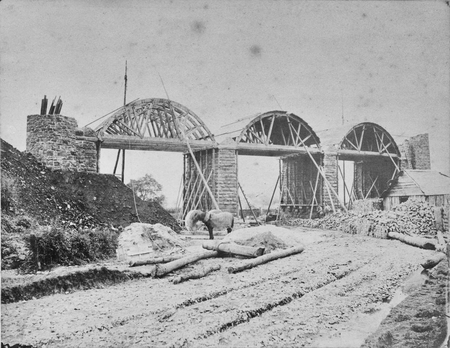
large_1998_8759_1_2b.jpg
For an arched viaduct, the abutments and intermediate piers are the first elements to be constructed and they must be founded on - and set within - solid bedrock. Once the 'springing point' has been reached, temporary supports must be erected to carry the weight of the arches while they are being formed. The 'formwork' visible in this photograph is nearing completion.
Image A3

large_1998_8759_1_2a.jpg
To define the curve of each arch and carry the weight of the masonry, the top surface of each set of formwork trusses is covered with timber boarding, laid at right angles to the trusses. In this photograph, the boarding for one of the arches is complete while the second is nearing completion. Note the line of wooden planks laid on the ground to create a walkway / barrow run across the muddy field (centre-right).
Image A4

large_1998_8759_1_3a.jpg
When constructing formwork trusses, the principles of triangulation are harnessed to provide maximum strength, while minimising the quantity and weight of component materials.
Image A5

large_1998_8759_1_3b.jpg
This photograph clearly illustrates how the tops of the formwork trusses are covered with boards to create the 'centering' for the arches. In the construction industry, temporary structures like this are often referred to as 'falsework' because, while essential to the construction process, they do not form part of the finished structure.
Image A6

large_1998_8759_1_4a.jpg
Wherever possible, stone and other construction materials were obtained from sources close to the worksite (to reduce transport costs). In this photograph, one of the stone quarries is clearly visible above the viaduct. The stone blocks have probably been shaped on the quarry floor and the resulting waste has been tipped down the adjacent slope.
Image A7

large_1998_8759_1_4c.jpg
Once the centering is in place, it can be used to support a temporary gantry crane and / or a raised section of railway. In this case, it is the latter, complete with a mobile crane in the process of positioning a large block of stone. Note too the vertical posts topped with cantilevered swivelling arms beside some of the arches: these are simple versions of a tower crane.
Image A8

large_1998_8759_1_4b.jpg
This is Monsal Head, immediately adjacent to the (as yet incomplete) Monsal Dale Viaduct (the site of which is visible in the bottom left corner). Work has begun on the creation of a cutting and the excavated rock is being tipped nearby to form the approach embankment for the viaduct. Drystone walls are being constructed along both sides of the cutting to form the railway boundary. Compare this photograph with Image A9.
Image A9

large_1998_8759_1_4d.jpg
The viaduct, embankment, cutting and drystone walls are all complete (but still looking fresh and raw) and all of the construction-related paraphernalia has been removed from the land at the base of the viaduct. The double-track railway formation is in place, fully ballasted and probably operational. Where the river passes between the piers, both river banks have been strengthened with graded rock.
Image A10
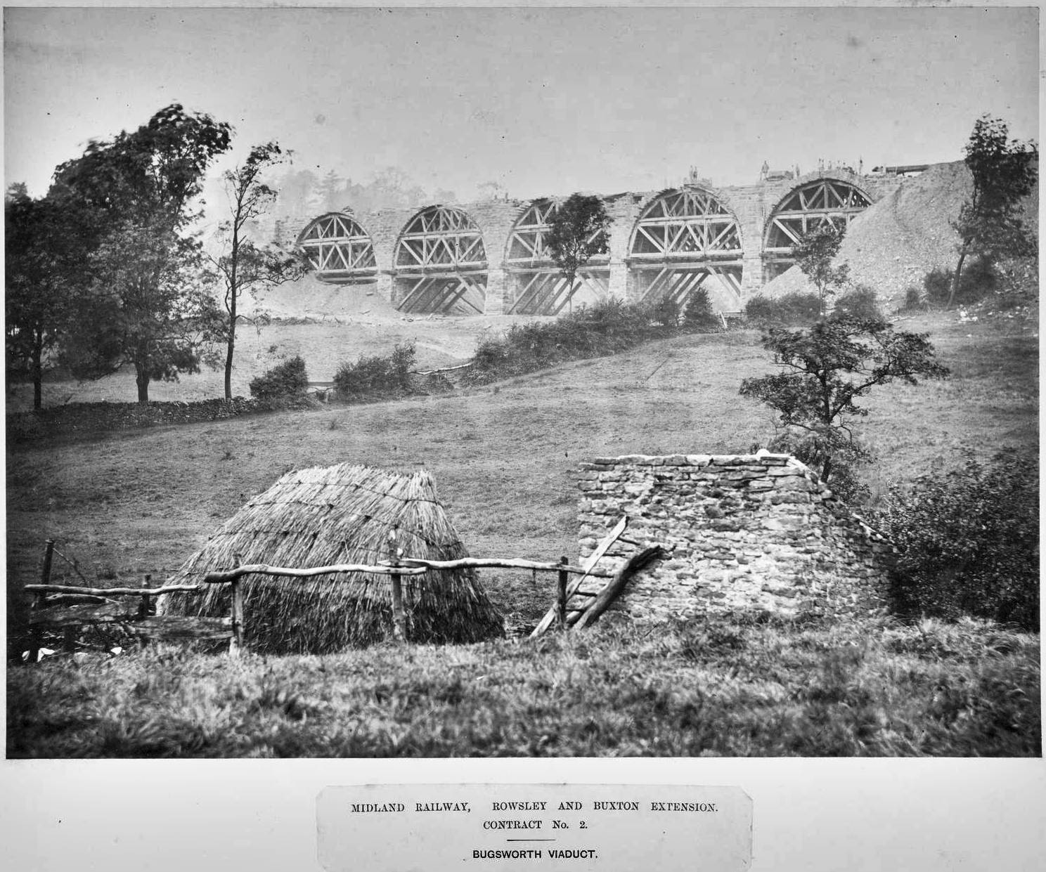
large_1998_8759_1_17.jpg
In this photograph, the idyllic rural scene in the foreground contrasts markedly with the construction site for the viaduct in the background. The latter was a powerful symbol of 'progress' and 'the modern world', so the arrival of railway builders in a remote community must have been quite a shock, even in 1860s.
Image A11

large_1998_8759_1_2c.jpg
This is almost certainly one of the four bridges across the River Wye on the Buxton line. (Bridges 7, 9, 11 & 12 were originally built to a very similar design.) The bridge was built as a free-standing structure, then the embankments were extended up to - and partly around - the two abutments.
Image A12
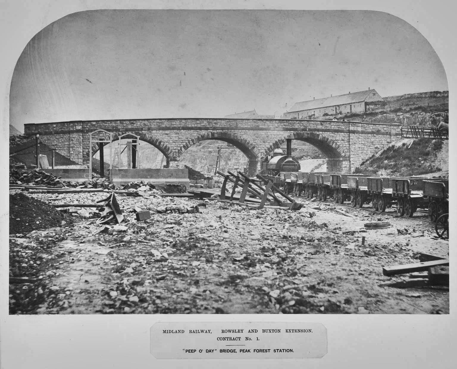
large_1998_8759_1_8.jpg
Trip-hazards galore on this rubble-strewn work site. The station area lies immediately beyond the bridge and the site is still being levelled. The upright skeletal structures in front of the bridge (left) are window or door frames for a new building, probably at the terminus of the Peak Forest Tramway.
Image A13

large_1998_8759_1_18.jpg
Construction work to create a short tunnel for the Midland Railway beneath the existing London & North Western Railway (L&NWR). Note the vertical shuttering beyond the tunnel mouth: this is probably the site of the initial cutting into the embankment to facilitate tunnelling beneath the L&NWR tracks. Compare this with Image A14.
Image A14
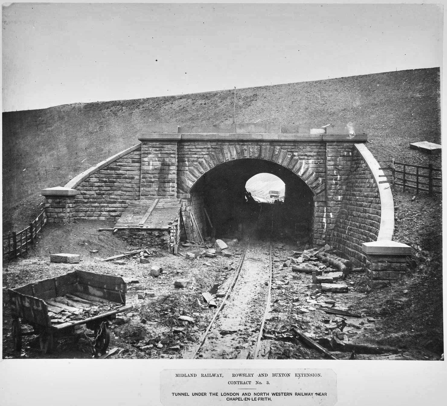
large_1998_8759_1_16.jpg
Since the previous photograph was taken (Image A13), the tunnel has broken-through, capping stones have been added to the wing walls & above the tunnel mouth, the vertical shuttering beyond the tunnel mouth has been removed, the temporary railway track has been singled and the fencing for the L&NWR line has been reinstated.
Image A15

large_1998_8759_1_7.jpg
The tunnel has broken through, but appears to be unlined and without portals or wing walls to protect against rock falls. Drystone walling has been erected around the tunnel mouth to protect livestock and mark the railway boundary. Note the two small rail-mounted mobile cranes near the tunnel mouth.
Image A16
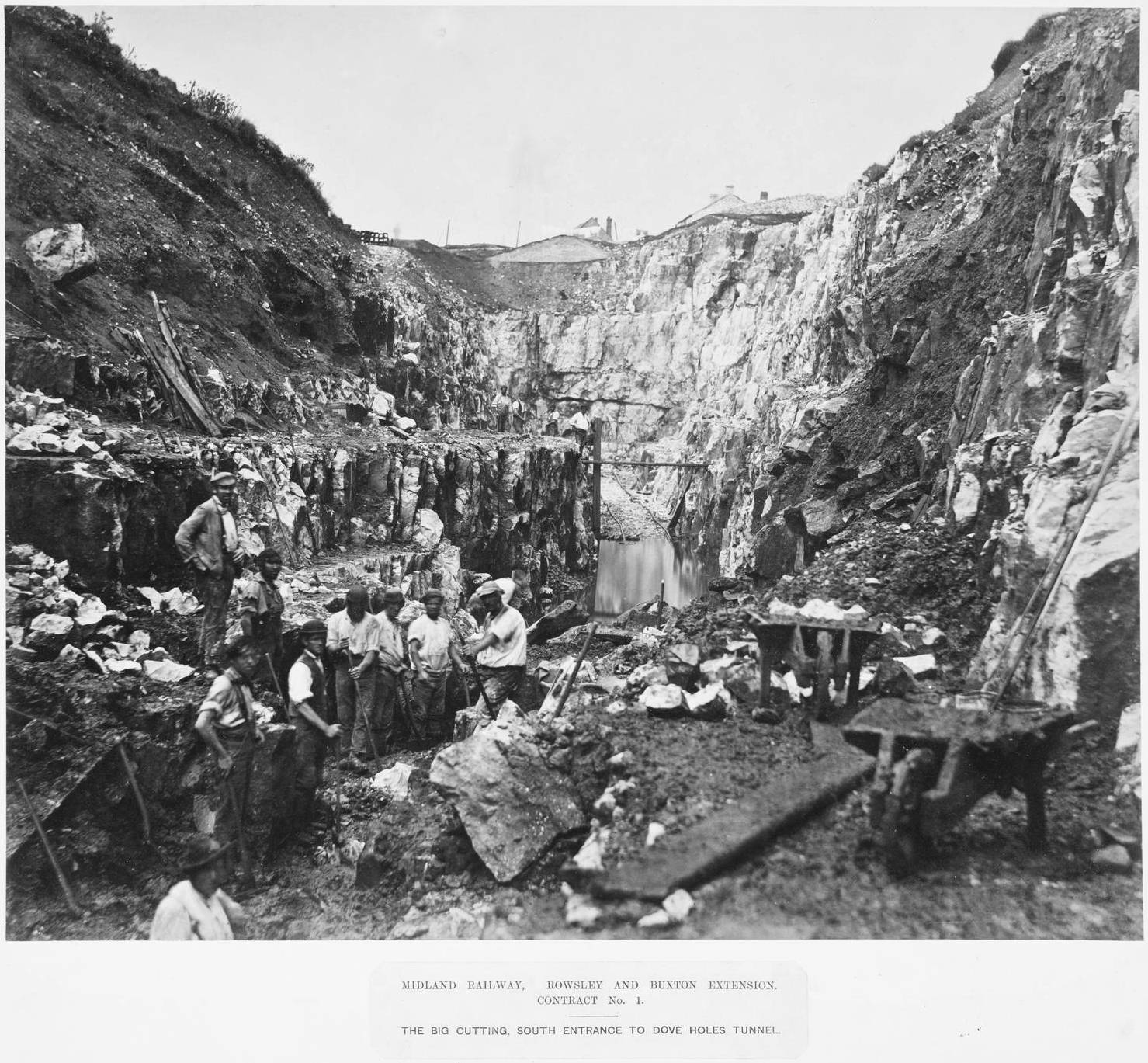
large_1998_8759_1_13.jpg
Hard graft and dirty work to boot. Close examination reveals that some of the men are holding hand-held rock drills, while others have the huge hammers used to strike the drills. In some cases, blocks of rock may fall away from the face with nothing more than brute force. In other cases, explosive assistance may be required.
Image A17

large_1998_8759_1_15.jpg
There are nearly as many horses as men in the middle ground of this photograph and they (men & horses) all need to be housed, fed and generally cared for. The head gear and chimney associated with one of the tunnel shafts can be seen on the distant hillside and the chimney of a second is visible on the skyline.
Image A18
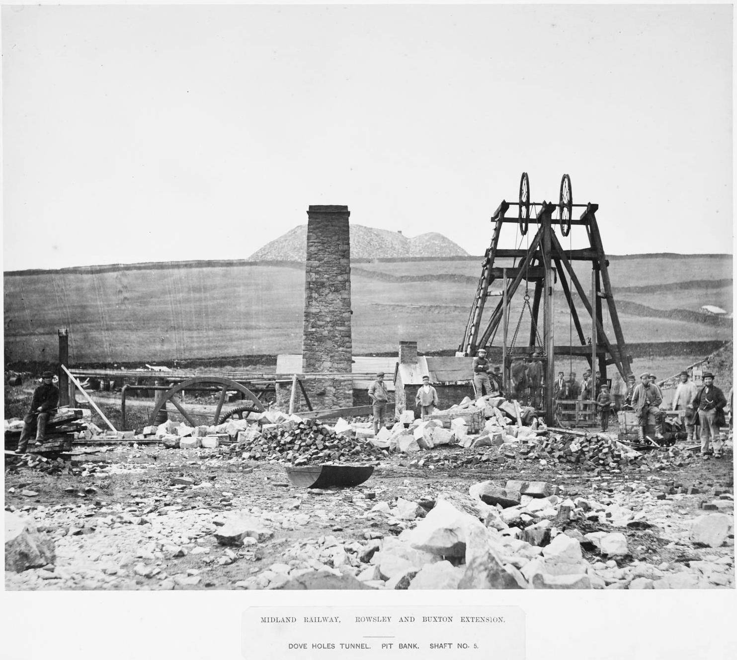
large_1998_8759_1_12.jpg
The most remarkable thing about this photograph isn't the wealth of fascinating detail around the shaft in the foreground, but the enormous size of the spoil heap on the horizon. All that broken rock has been hewn by hand from two faces at the foot of the distant shaft, then hauled up to the surface to be tipped.
Image A19

large_1998_8759_1_14.jpg
The man sitting in the foreground is probably a stonemason, preparing blocks to line the tunnel. Immediately behind him is an empty tipper wagon. Above his head, a man is pushing a second empty tipper wagon onto the lift above the shaft: it will be lowered into the tunnel, filled with spoil, then returned to the surface for emptying.
Image A20

large_1998_8759_1_10b.jpg
Close inspection of this photograph will reveal a completely open lift platform at the head of the unguarded shaft. The surface of the lift platform seems to include a pair of rails or guides for the spoil wagons. The manner in which the platform is attached to the cable is also worthy of close inspection: a ring, four chains and a timber frame.
Image A21

large_1998_8759_1_10a.jpg
This may have been a wet tunnel as there appear to be a pair of linked cast iron beams at the shaft head, which may be harnessing the power of the steam engine to operate a pair of water pumps. Also worthy of note is the very rudimentary 'ladder' providing access to the head gear for maintenance. The wooden fence around the site was probably installed to keep-out livestock, rather than to protect humans.
B: Bedford to London
Image B1
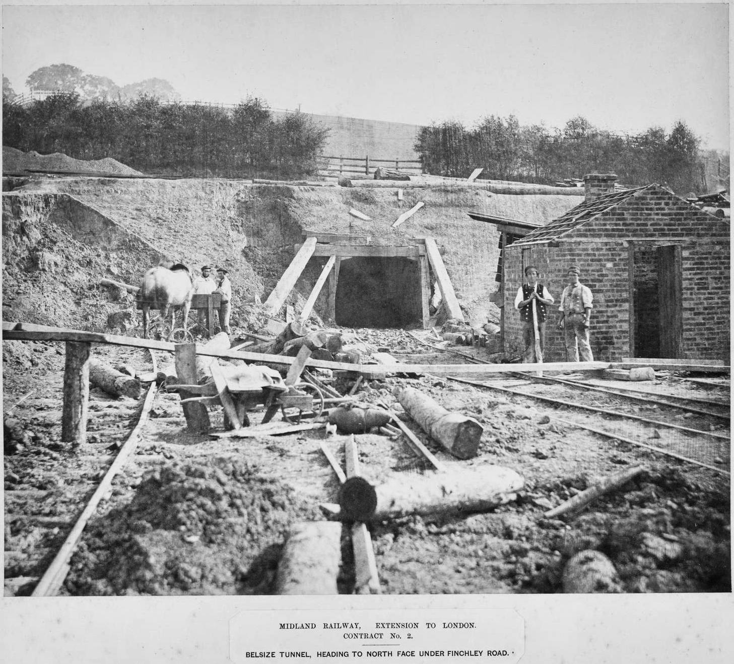
large_1998_8759_2_18.jpg
This heading will become the western portal of the tunnel. The loose earth around the heading is supported by a few timber props: simple by today's standards, but probably very effective (except perhaps during heavy rain). All of the temporary railway tracks are currently obstructed and those near the heading appear to be well out of gauge.
Image B2
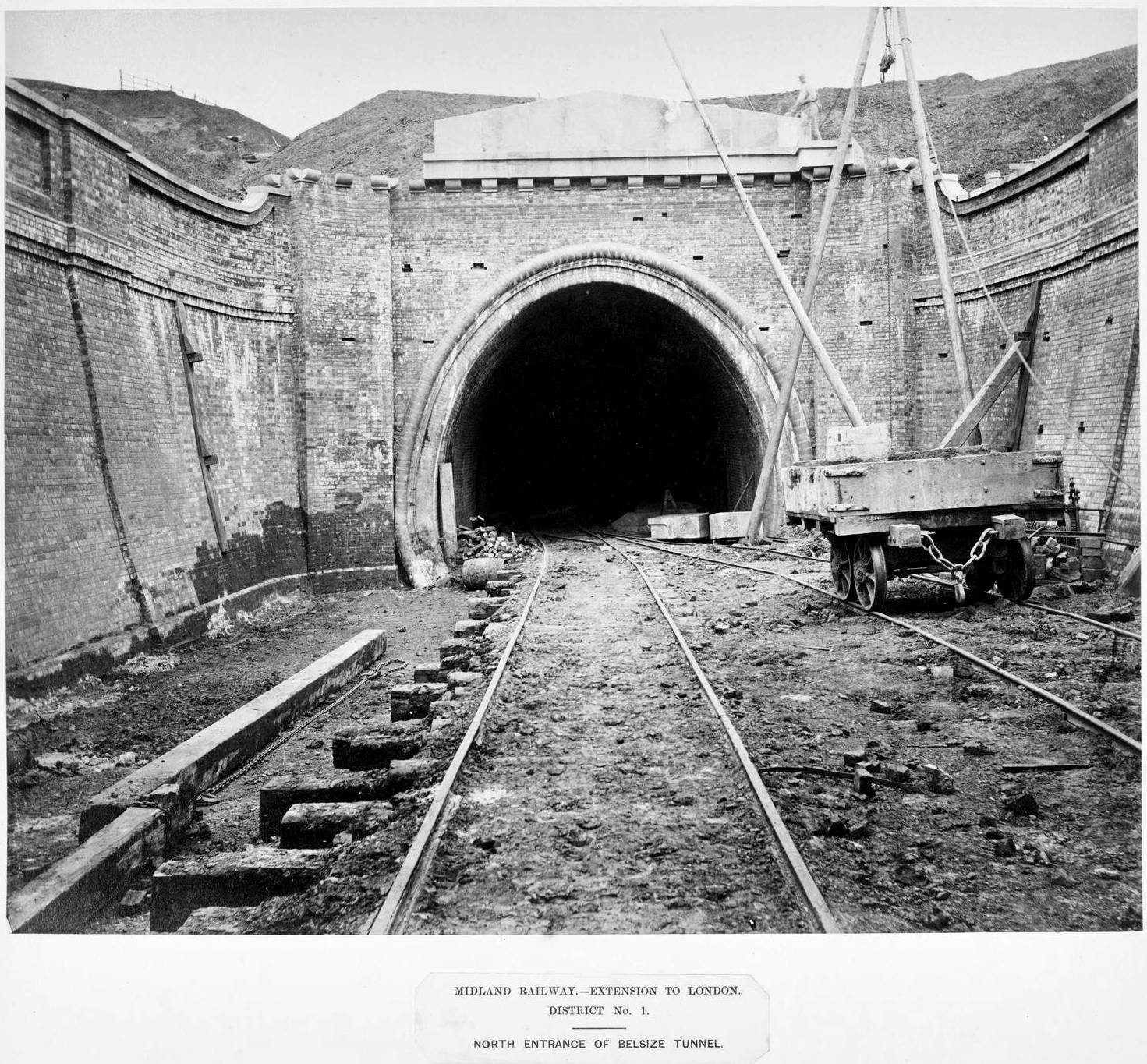
large_1998_8759_2_7.jpg
This is the eastern portal. Note the temporary rail tracks, what appears to be an A-frame crane or hoist (right), the holes in the brickwork (which stabilised the timber scaffolding used by the bricklayers) and the remains of the temporary timber props that supported the retaining walls (left & right) while the mortar dried.
Image B3

large_1998_8759_2_8.jpg
The eastern approaches to the tunnel run through a deep cutting. A series of five 'strainer arches' help the brick retaining walls resist the lateral thrust of the earth on either side and four of these arches are clearly visible in this photograph. The more circular form of the eastern tunnel mouth (see Image B2) is visible in the distance. It is reassuring to note that there is light at the end of this particular tunnel.
Image B4

large_1998_8759_2_17.jpg
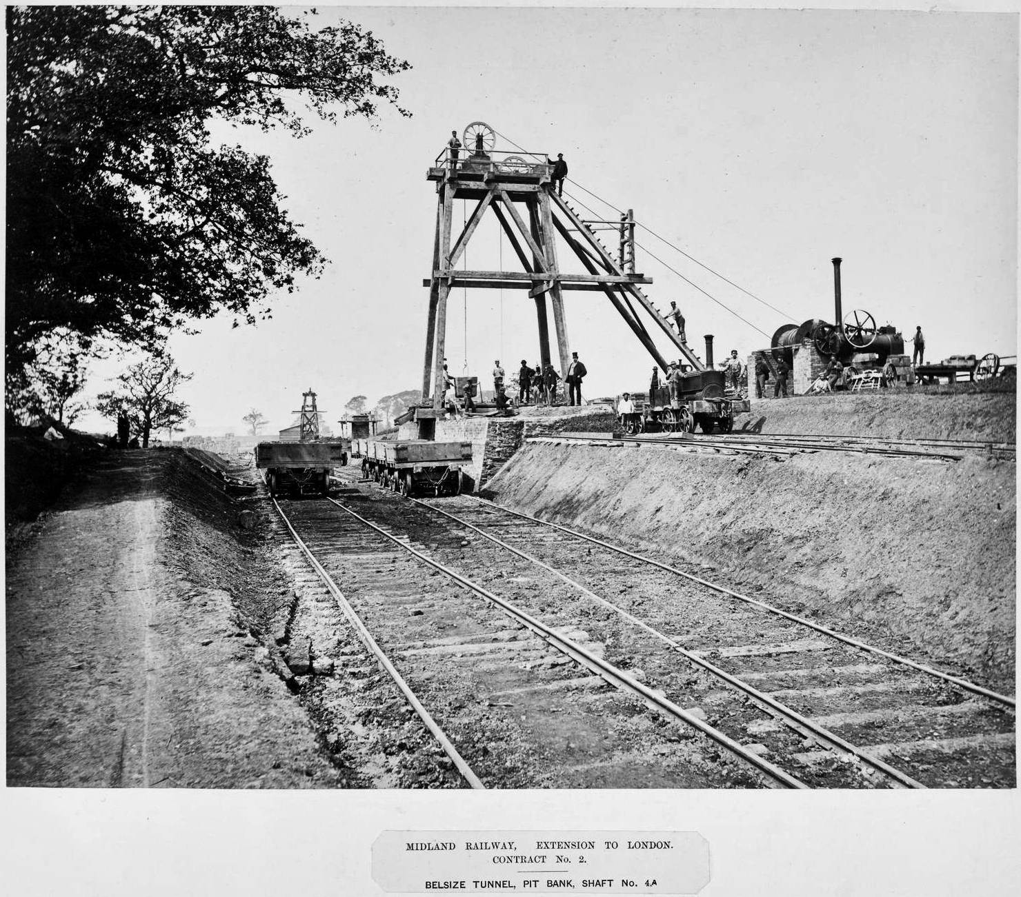
During this period, most shafts associated with tunnelling would have featured very similar equipment including a shaft (usually lined with timber to prevent loose rock falling onto the men below), head gear, a windlass, horse gin or steam engine (for raising & lowering things) and a tramway or railway for moving spoil & equipment.
Image B5
large_1998_8759_2_22.jpg
Some of the steam engines were housed in rudimentary shelters (e.g. the one in Image B4) while others (like this one) were open to the elements. The temporary railway arrangements serving this series of shafts appear to have been quite extensive and a comparatively wide track gauge appears to have been used.
Image B6
large_1998_8759_2_23.jpg
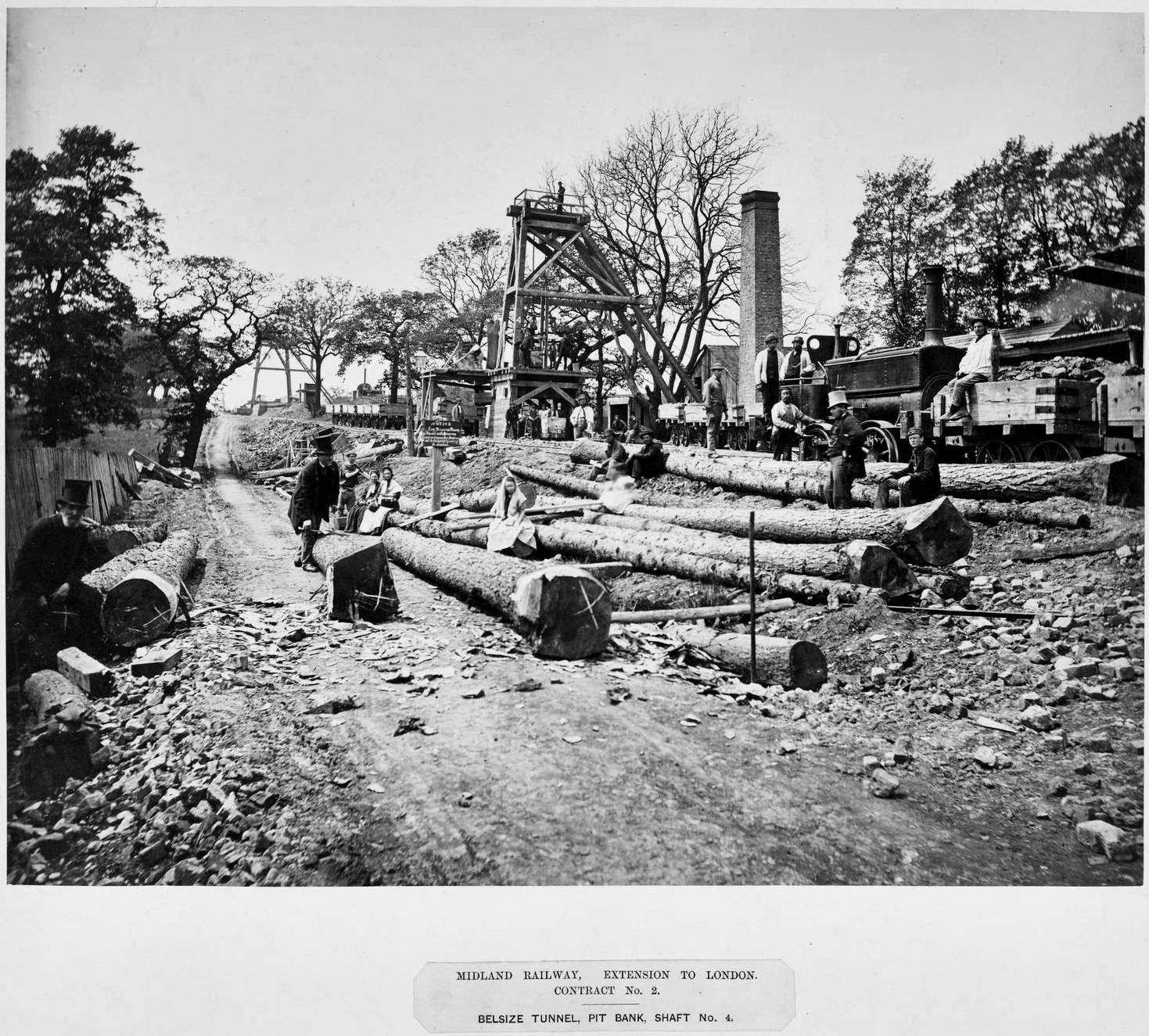
Things to note in this photograph include the large number of posing workers (who appear to be wearing their 'Sunday best'), the contractor's locomotive (with its spectacled cab front and an oil-can wielding attendant) and the huge tree trunks (perhaps waiting to be sawn into props or new support timbers for the head gear).
Image B7
Winding gear at Belsize Tunnel, about 1865
large_1998_8759_2_25.jpg
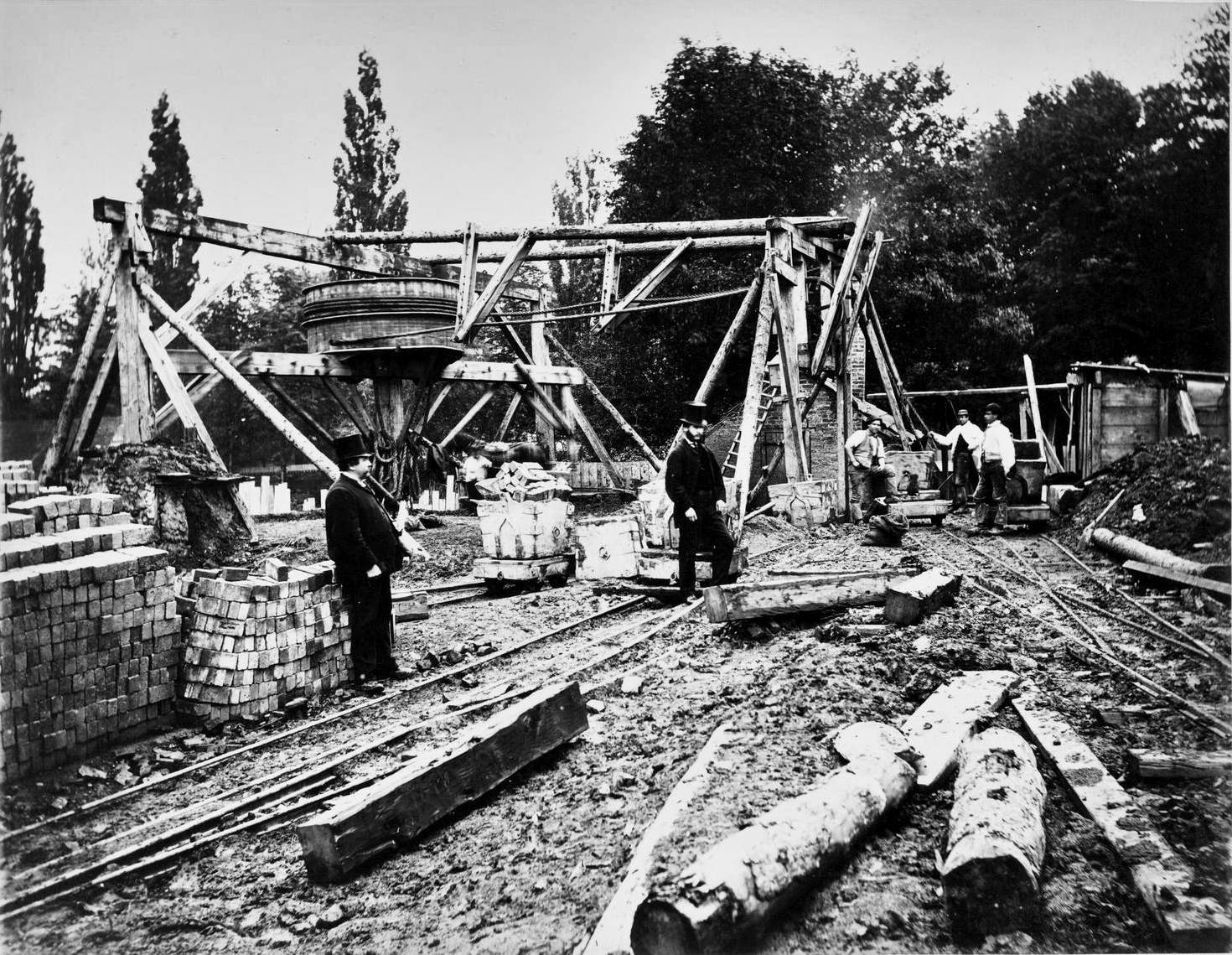
The 'winding gear' pictured in Images B7 & B8 is a 'horse gin'. A horse is harnessed to each end of the long timber beam that is visible immediately below the horizontally oriented winding drum. One end of a rope or cable is attached to the winding drum. The other end is fed through a pulley above the shaft and attached to a bucket, tub, or platform. ...
Image B8

large_1998_8759_2_26.jpg
... As the two horses are led round in a circle by their keepers, the winding drum revolves and either hauls-up or controls the descent of the load. Horse gins were typically used for shallow shafts with short headings or at new sites until a steam engine could be installed.
Image B9

large_1998_8759_2_20.jpg
On steeply sloping sites, railway / tramway locomotives cannot gain sufficient traction to operate without rack & pinion or other cog-based systems (which are expensive and time-consuming to install). In such circumstances, static winding engines could be installed to haul the trucks up and control their descent, as pictured here.
Image B10

large_1998_8759_2_12.jpg
They appear to be constructing a curved profile retaining wall with relieving arches to support the unconsolidated material that forms the side of the cutting. Note the huge quantities of timber shoring and the timber scaffolding. The horizontal members of the latter are simply lashed to the uprights with rope.
Image B11
large_1998_8759_2_14.jpg
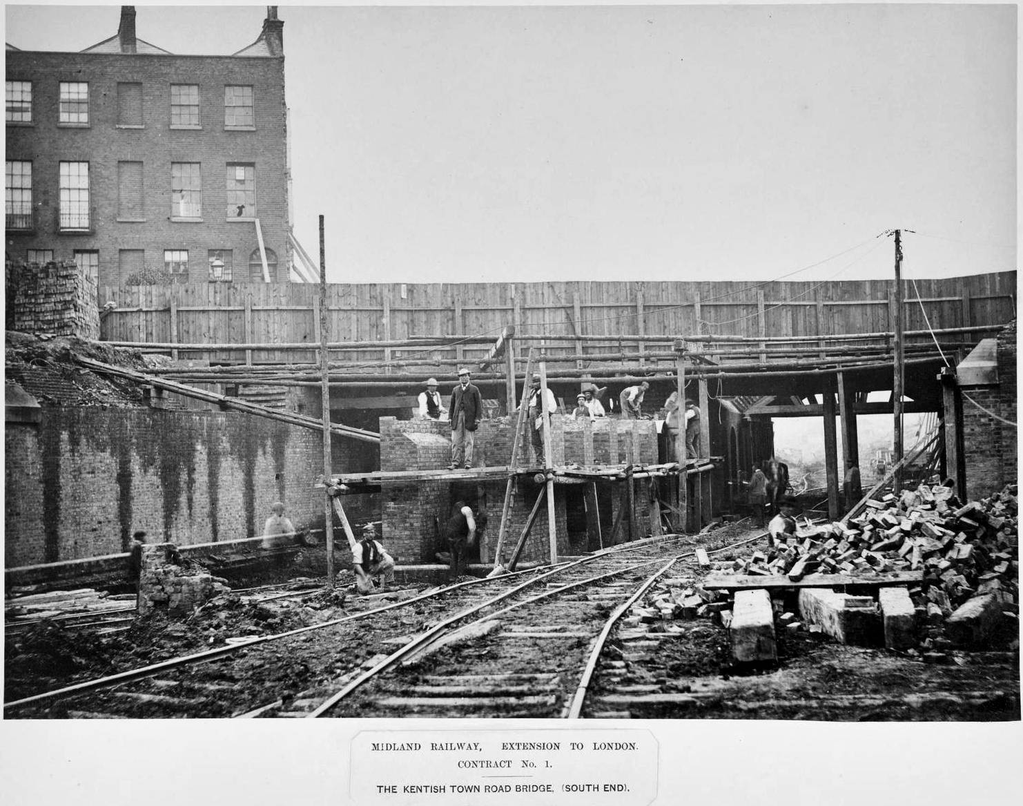
These men are building the central pier of an overbridge. Once again, note the simple (unguarded) timber scaffolding that is being used as a working platform. Mud, rubble and uneven temporary railways / tramways seem to have been typical conditions on virtually all 1860s work sites. The people in most of these photographs seem to be wearing a variety of soft (rather than hard) hats.
Image B12

large_1998_8759_2_15.jpg
Perhaps the most noteworthy items in this photograph are the junctions where two railway tracks meet. There are no turnouts (a.k.a. points). Instead, a section of track would have been disconnected, slewed over from one track to the other then reconnected. Not a quick process, but clearly adequate for their needs.
Image B13

large_1998_8759_2_5.jpg
More accurately, inserting a bridge to allow the Midland line to pass beneath the existing North London Railway line. Note the pair of horses awaiting their next task (left), the neat piles of new bricks (centre) and what appears to be a pile of building sand, with a full wheelbarrow on the wheelbarrow run (right).
Image B14

large_1998_8759_2_31.jpg
This photograph clearly shows a simple 'gin pole' (the precursor to the modern crane) in operation lifting a section of bridge deck. Note also the contractor's locomotive, somewhat overmanned with four footplate crew. However, they can perhaps be forgiven as this is an 'official' photo (which is why no one is moving).
Image B15

large_1998_8759_2_13.jpg
This is a brick-making machine. Shovel-in a suitable mix of clay and other essential ingredients at the top and unfired bricks pop out of the end, ready for drying and firing. Note the wire brick cutter (centre-right), the timber barrow runs (bottom) and the purpose-built brick barrows (centre and centre-left).
For photographs and information relating to the construction of the London terminus, see 'A brief time-travelling excursion to London St. Pancras'.
Footnotes & acknowledgements
[1] The original images can be viewed at:
https://collection.sciencemuseumgroup.org.uk/objects/co442043/photographs-of-the-works-in-progress-of-the-midland-railway-photographs.
[2] The Rowsley & Buxton line (via Blackwell Mill) was authorised by Parliament on 25th May 1860. An extension of that line from Blackwell Mill to New Mills was authorised in 1862. The line from Rowsley to Buxton officially opened on 30th May 1863 for goods traffic and 1st June for passenger traffic. Work on the section from Blackwell Mill to New Mills was completed in October 1866, but a significant landslip at Bugsworth caused the line to be closed almost immediately. It was reopened on 1st February 1867.
[3] The London extension (from Bedford to St. Pancras) was authorised by Parliament in 1863 and the full route opened in 1868.
[4] The status of the Science Museum catalogue descriptions and original filenames is unclear, but they are almost certainly either released under Creative Commons Zero:
https://creativecommons.org/publicdomain/zero/1.0
or shared under the Creative Commons Attribution-NonCommercial-ShareAlike 4.0 Licence:
https://creativecommons.org/licenses/by-nc-sa/4.0.
The supplementary notes / comments below the catalogue descriptions and original filenames were researched and written by Mark R. Harvey and they are protected by copyright: © Mark R. Harvey (2022).
Further reading
[A] Hudson, Bill: "Through Limestone Hills: The Peak Line - Ambergate to Chinley", Oxford Publishing Co. (1989).
[B] Williams, Frederick Smeeton: "The Midland railway: its rise and progress. A narrative of modern enterprise", Strahan & Co London (1876). A 42Mb pdf version of this book can be downloaded from:
http://www.archive.org/details/midlandrailwayit00will.
See also "Photographs relating to the construction of the Settle & Carlisle Railway".
