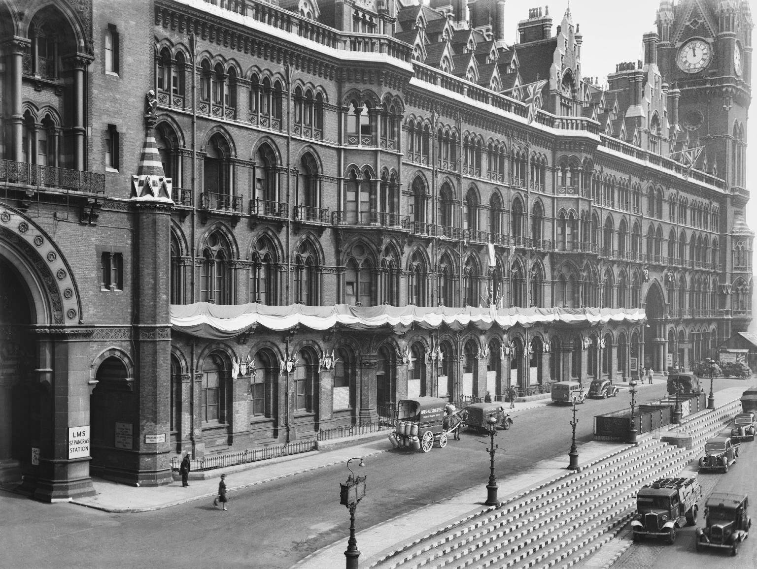
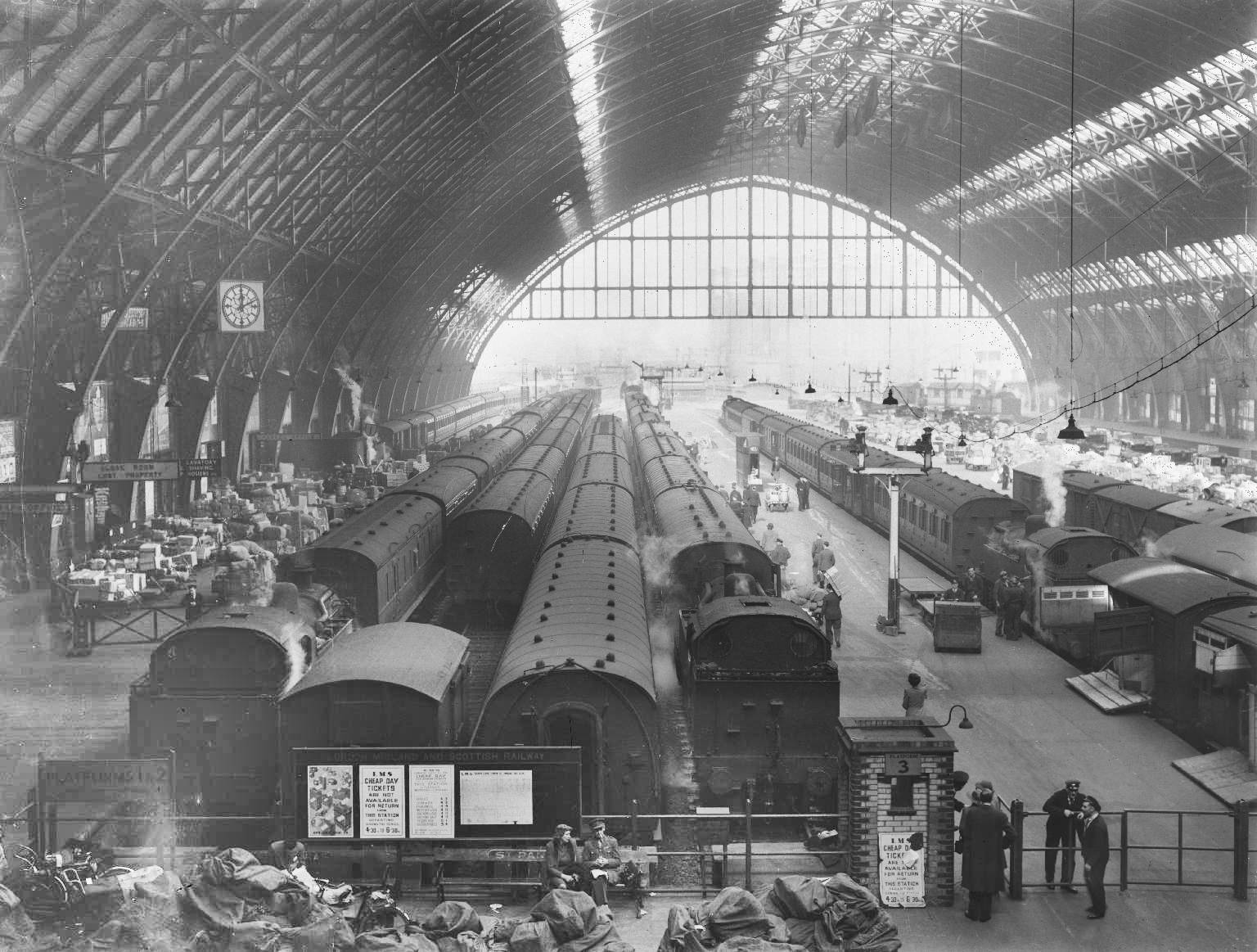
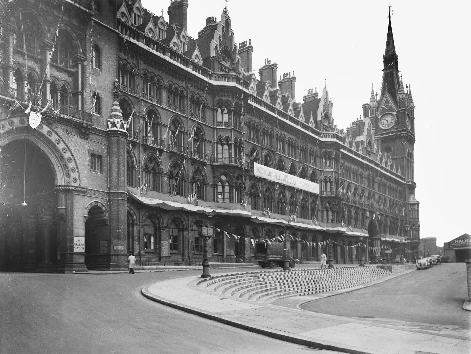
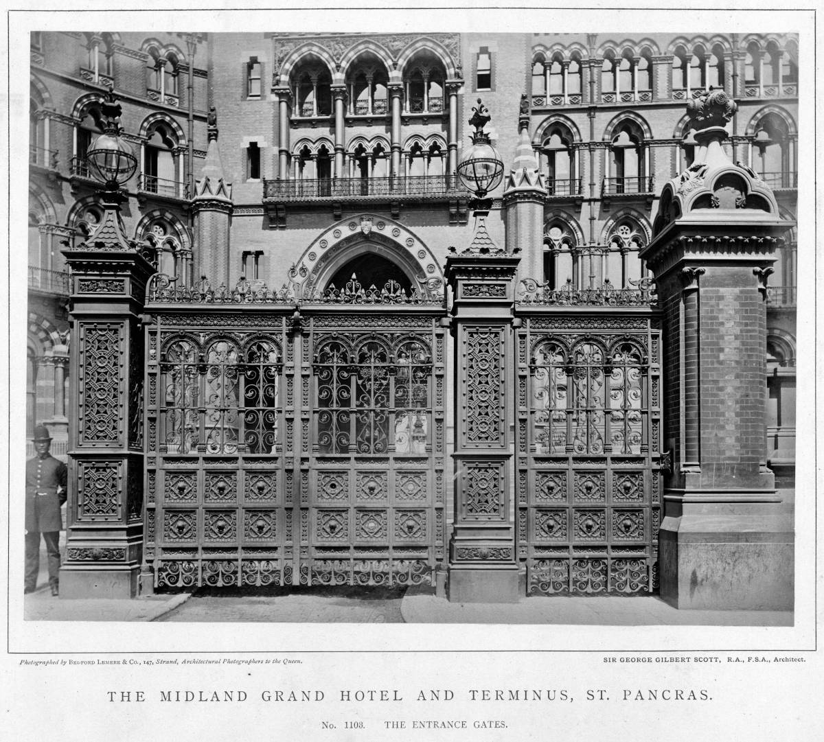
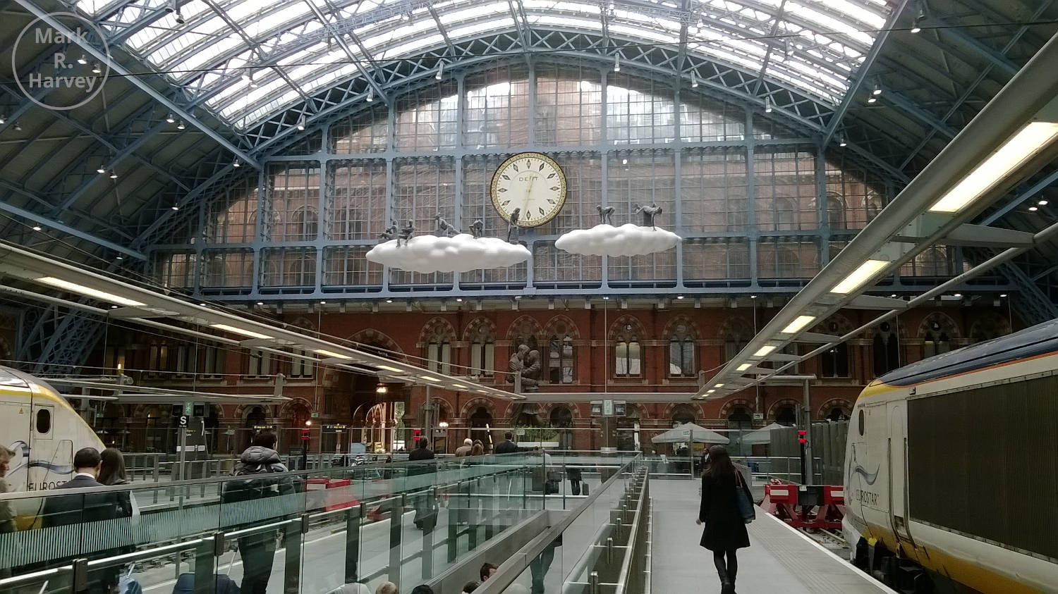
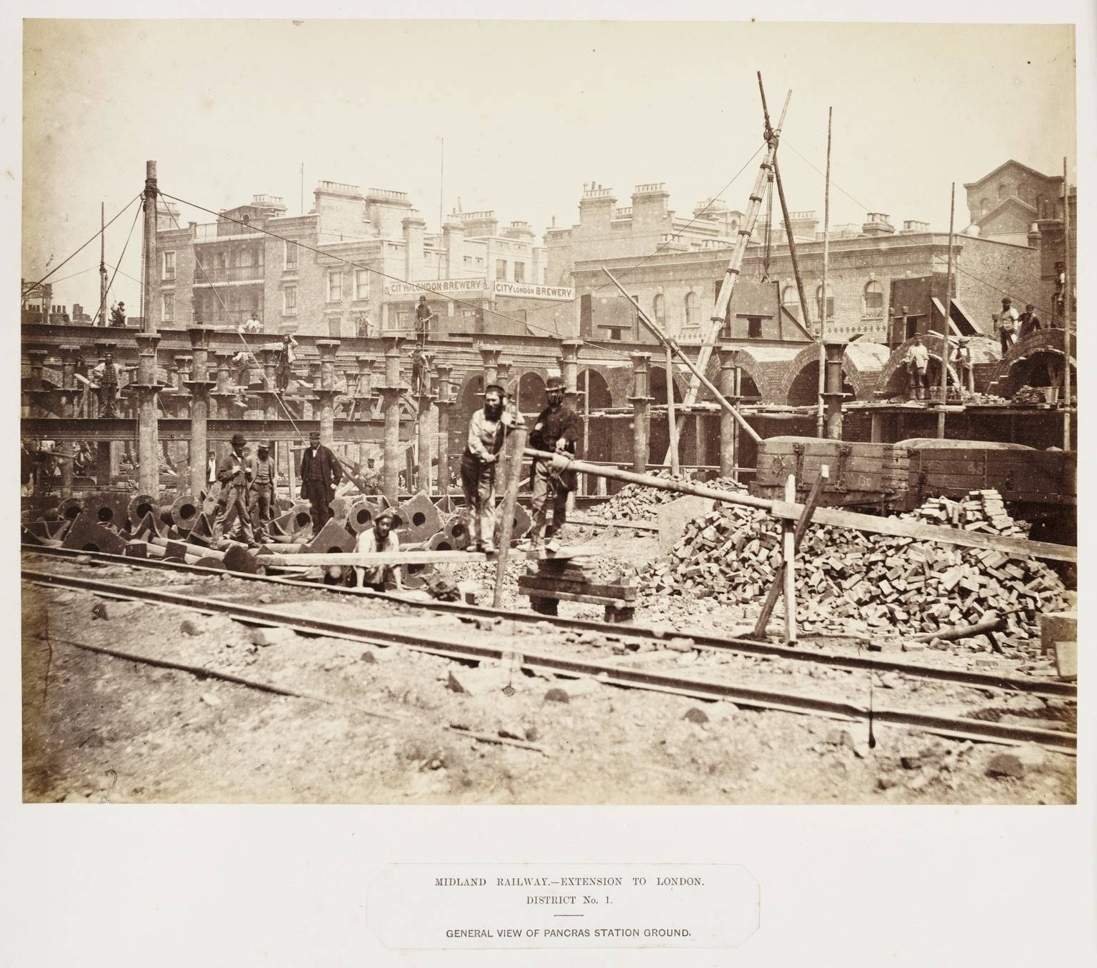
This page has been created primarily to share a set of photographs from the 'Science Museum Group Collection Online' that span a period of around 80 years, from the station's construction in 1866-1876 to the first year of British Railways in 1948.
All of these images are fascinating in their own right, but the photographs taken during the construction period are especially valuable as they provide an insight into some of the equipment, construction methods and worksite conditions that would have been associated with the building of the Settle & Carlisle Railway (1869-1876) and the current stations at Hellifield (1880) and Carlisle (1878-1880).
The images are split into sections based on their source, captions have been added for the construction-era images and a short introduction has been provided to put the images into context and aid interpretation. Where appropriate, the catalogue descriptions and original filenames are provided in italics.
Introduction
St. Pancras station was built by the Midland Railway to provide a London terminus for its extensive and rapidly expanding network of passenger routes. Constructing the station was an incredibly complex task.
- Parts of the site lie above the Fleet Sewer and this had to be rerouted and transferred into a new iron tunnel.
- A new tunnel had to be constructed for the second line of the Metropolitan Railway (at the front of the site, parallel with the Euston Road and beneath what would become the front approach ramp for the station, Midland Railway offices and Grand Hotel).
- A double-track tunnel had to be constructed for the St. Pancras branch (a new section of railway linking the Metropolitan and Midland lines) and this had to pass below the Midland's approach lines, the Fleet Sewer and the Midland's station .
- The Midland's approach lines had to cross the Regent's Canal (just beyond the station) without obstructing boat traffic.
Taken together, these complications dictated that the height of the rails within the station needed to be 12 to 17 feet above the level of the adjacent roads. Rather than build-up the ground with earth and broken rock, the decision was taken to construct an undercroft as this created valuable extra space for goods handling, warehousing and retail units.
A brief look at the two plans below should help to clarify how the key features of this complex site fit together.
Figure 1
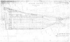
Figure 2

Site clearance and preparatory works commenced in 1866 but, due to the complexity of the ground works, it was January or February 1868 before the Butterley Company could begin installing the cast iron columns to support the train shed floor (starting from the north end). The train shed roof was substantially complete by September 1868 and the platform areas of the station opened to passenger traffic on October 1st, 1868. In his well regarded history of the Midland Railway [E], F.S. Williams furnishes us with some impressive statistics for the project:
For its passenger station alone it swept away seven streets of three thousand houses, and a church; Old St. Pancras Churchyard was invaded; and Agar Town was almost demolished.
... The work of 100 steam lifts, 1000 horses, and 6000 men, tell their tale.
... Of the magnitude of the work generally, some idea may be gathered from the fact that in the station and its approaches some 60,000,000 of bricks, 9000 tons of iron, and 80,000 cubic feet of fourteen different kinds of dressed stone have been employed.
It may be interesting to add that the twenty-four main ribs, with bolts, ornamental spandrils, etc., cost something more than £1000 apiece.
Work on the hotel and station offices progressed at a much slower pace and the hotel was not completed until the summer of 1876. According to F.S. Williams [E], the delay was a consequence of the 'Black Friday' financial crisis (11th May 1866) combined with the cost and timescale implications of George Gilbert Scott's lavish design.
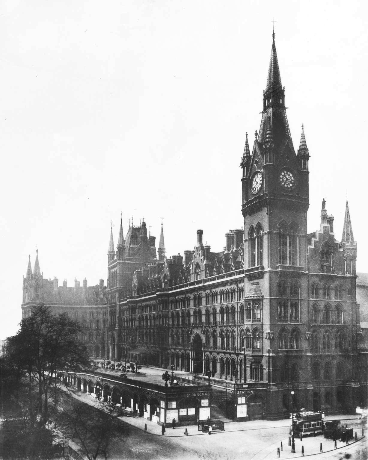
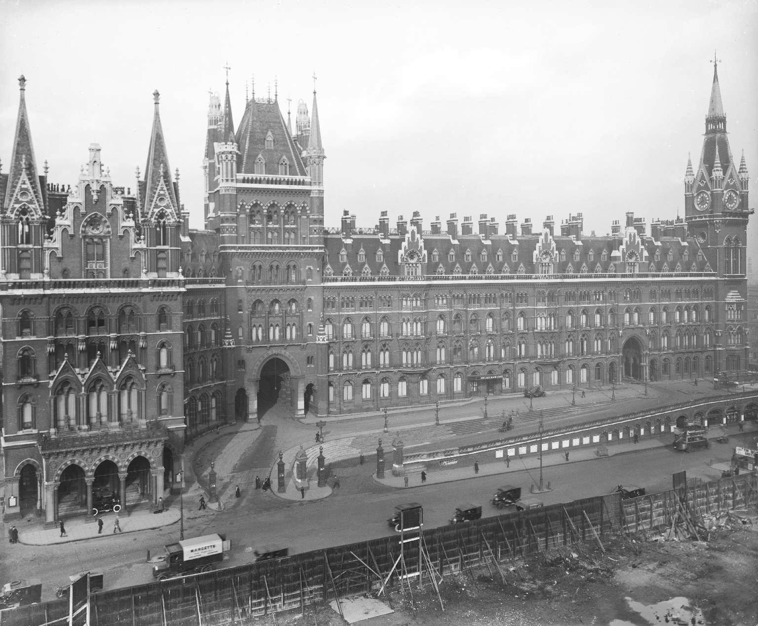
Between 2003 and 2007, the operational areas of the station and its approaches were significantly altered as part of the Channel Tunnel Rail Link / High Speed 1 project. The £800m redevelopment programme included the restoration of Barlow's train shed, the construction of a 240 metre long extension to the northern end of the train shed, the complete rebuilding of the west wall and the conversion of the undercroft into a new station concourse and shopping centre. At around the same time, Scott's combined hotel & station building was the subject of a separate £200m redevelopment project and it now accommodates 68 luxury apartments and a luxury hotel - the latter opening for business on May 5th, 2011.
Photographs of the Works in Progress of the Midland Railway
The images in this section are photographs sourced from the Science Museum Group Collection Online on July 27, 2022 (collection reference 1998-8759). All of these images have been edited to increase contrast, reduce the glare introduced during the digitisation process and thereby significantly increase the amount of visible detail and they are shared under the Creative Commons Attribution-NonCommercial-ShareAlike 4.0 Licence - see
https://creativecommons.org/licenses/by-nc-sa/4.0.
Image 1
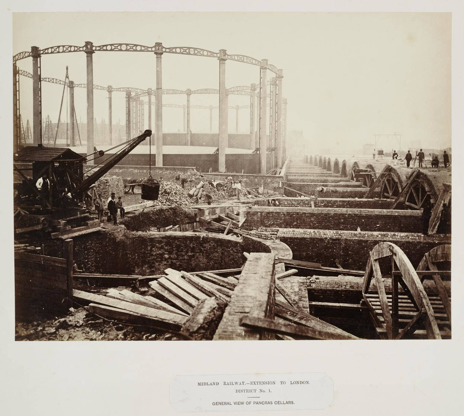
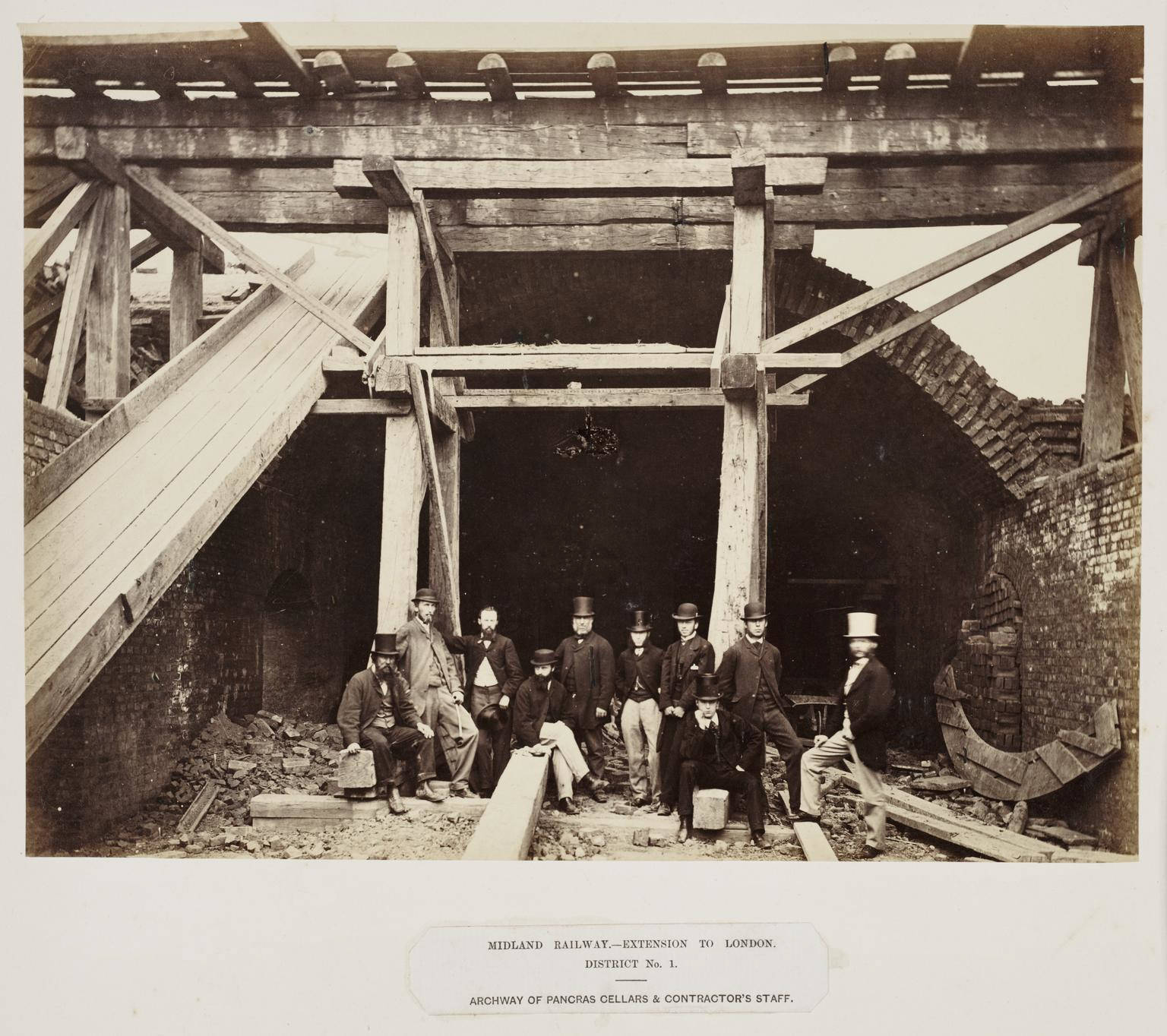
St Pancras cellars, 1867.
large_1998_8759_2_35.jpg
Image 2
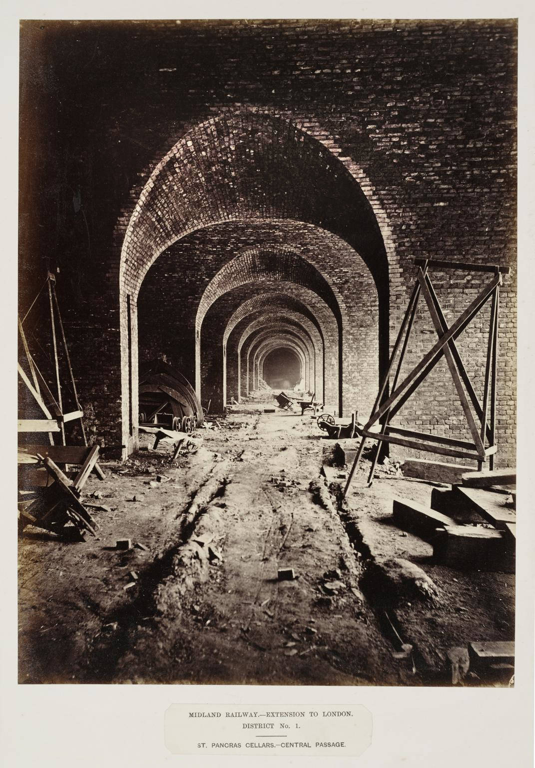
St Pancras cellars, 1867.
large_1998_8759_2_36.jpg
Image 3
Railway contractor's staff, about 1867.
large_1998_8759_2_30.jpg
Image 4
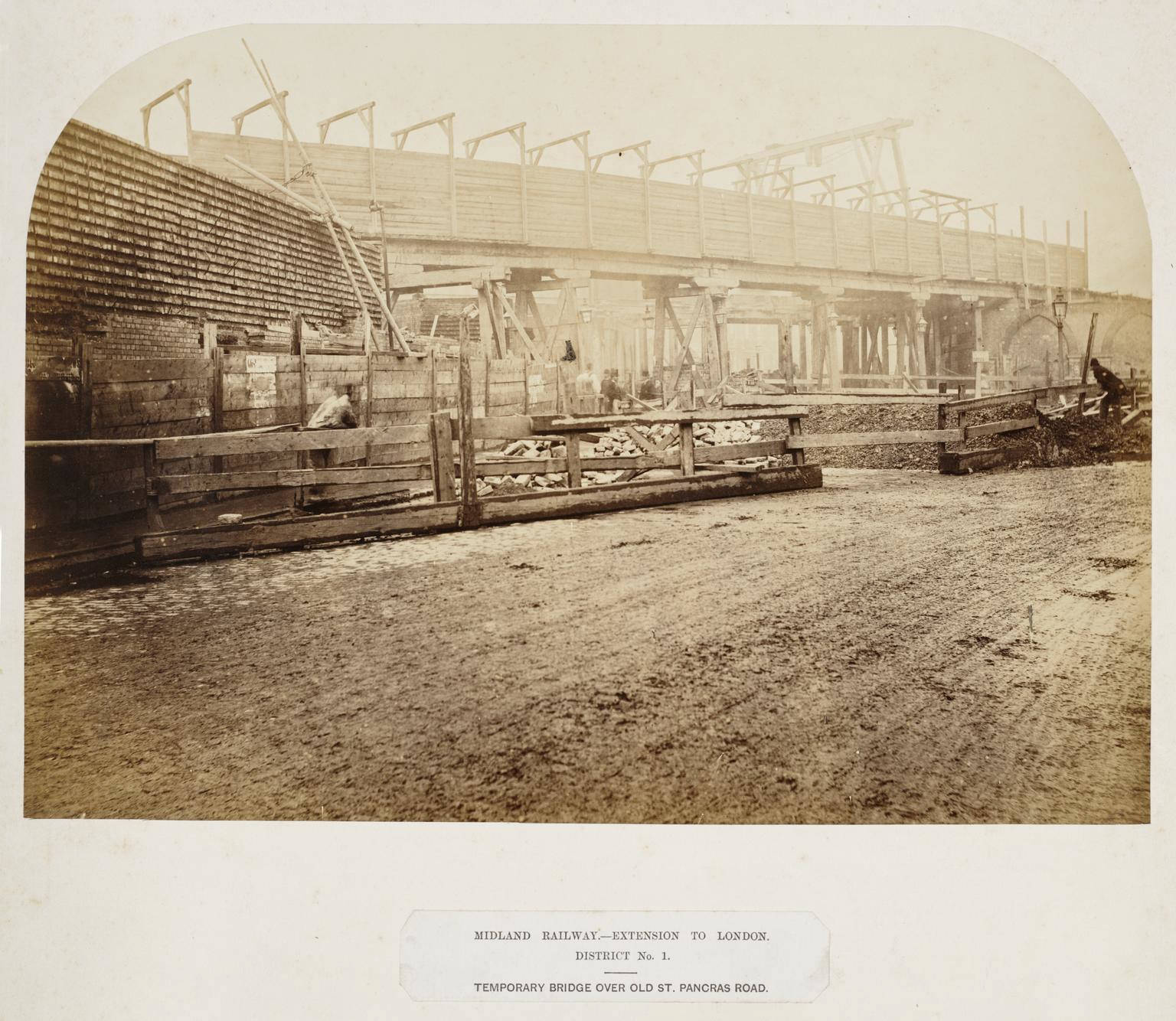
Bridge over Old St Pancras road, about 1867
large_1998_8759_3_2.jpg
Image 4a
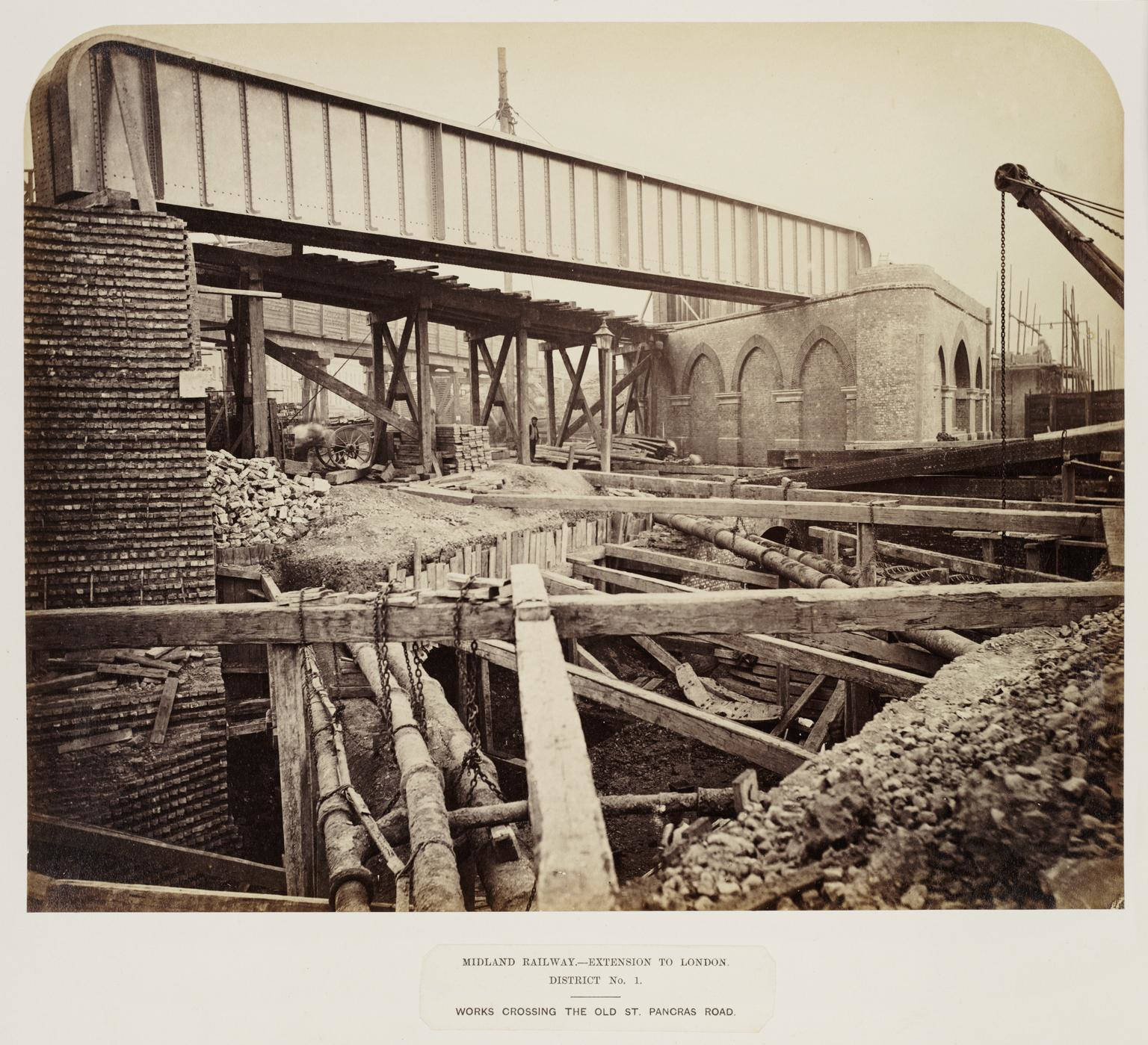
Incorrectly described as Works crossing the Old St Pancras burial ground
large_1998_8759_3_22.jpg
Image 5
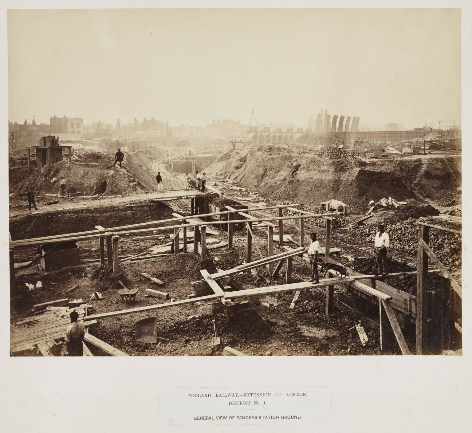
Construction of St Pancras railway station, 1867.
large_1998_8759_2_34.jpg
Image 6
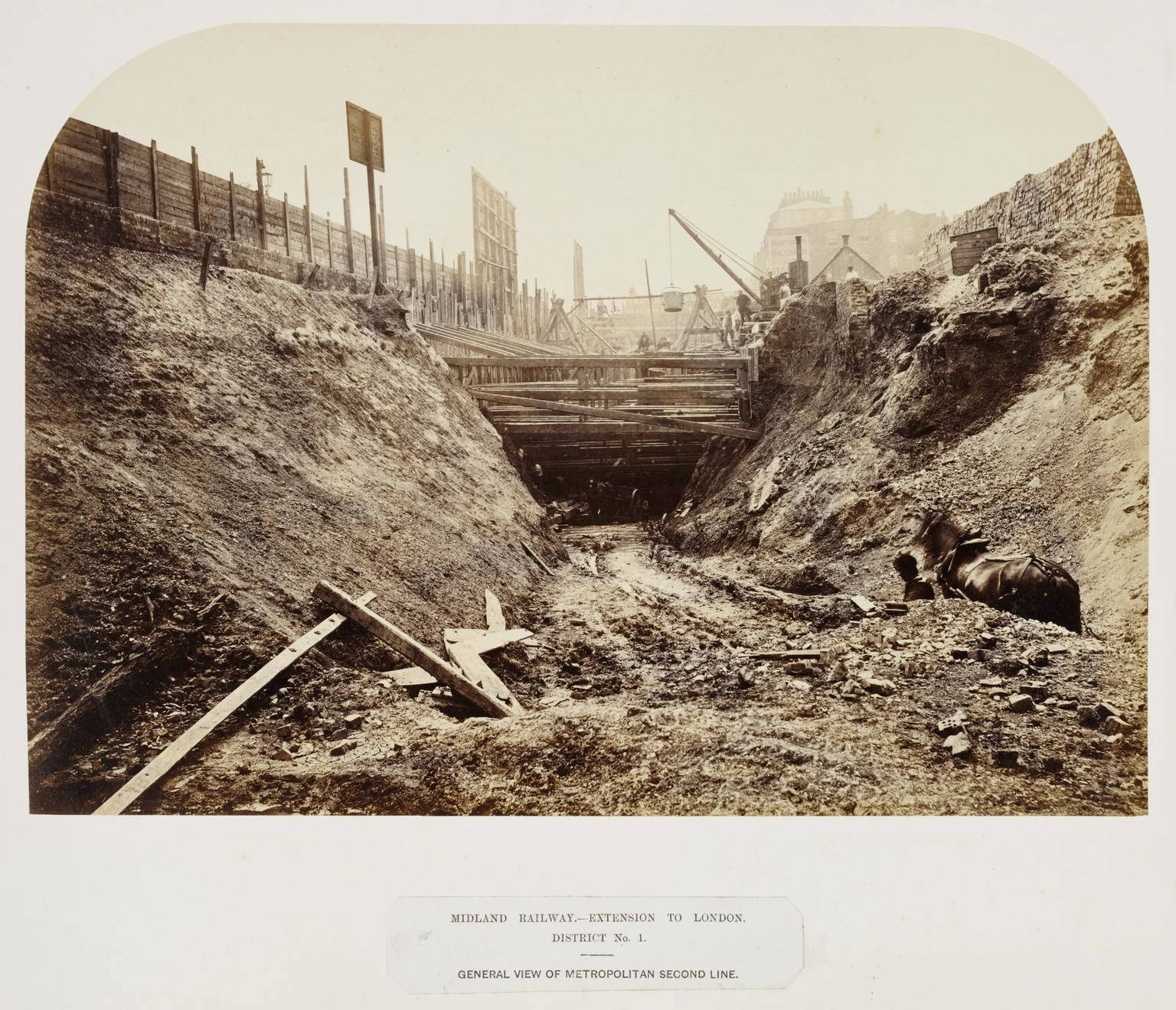
Construction on the Metropolitan Railway, about 1867.
large_1998_8759_2_38.jpg
Image 7
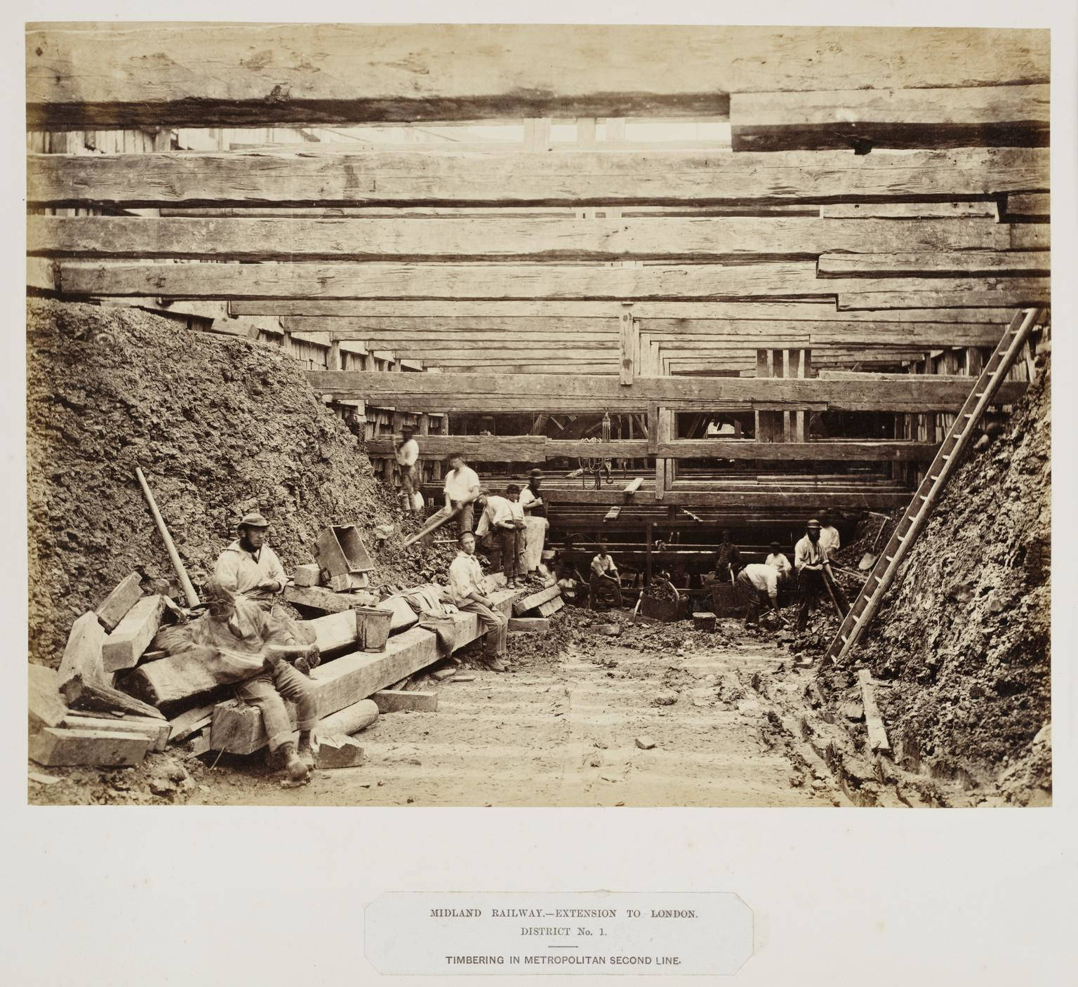
Metropolitan Railway, about 1867.
large_1998_8759_2_37.jpg
Image 8
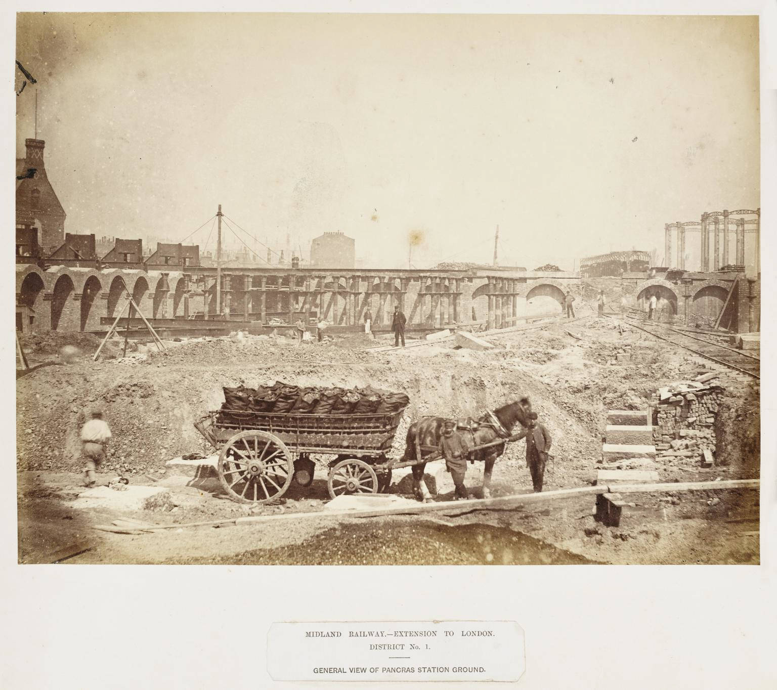
Site of St Pancras station, about 1867.
large_1998_8759_3_3.jpg
Image 9
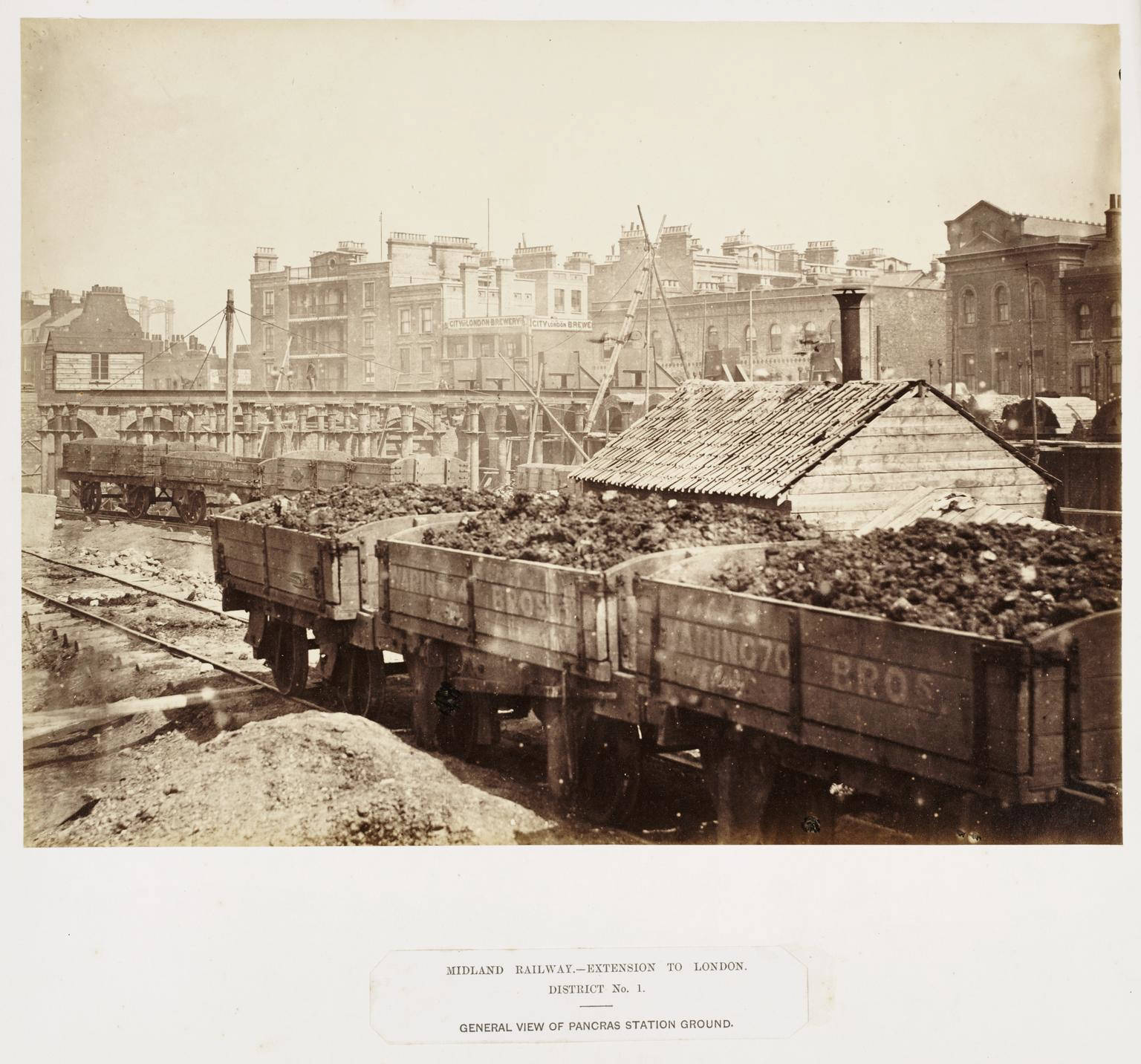
"Construction of St Pancras station, about 1867."
large_1998_8759_3_5.jpg
Image 10
Construction of St Pancras station, about 1867.
large_1998_8759_3_4.jpg
Image 11
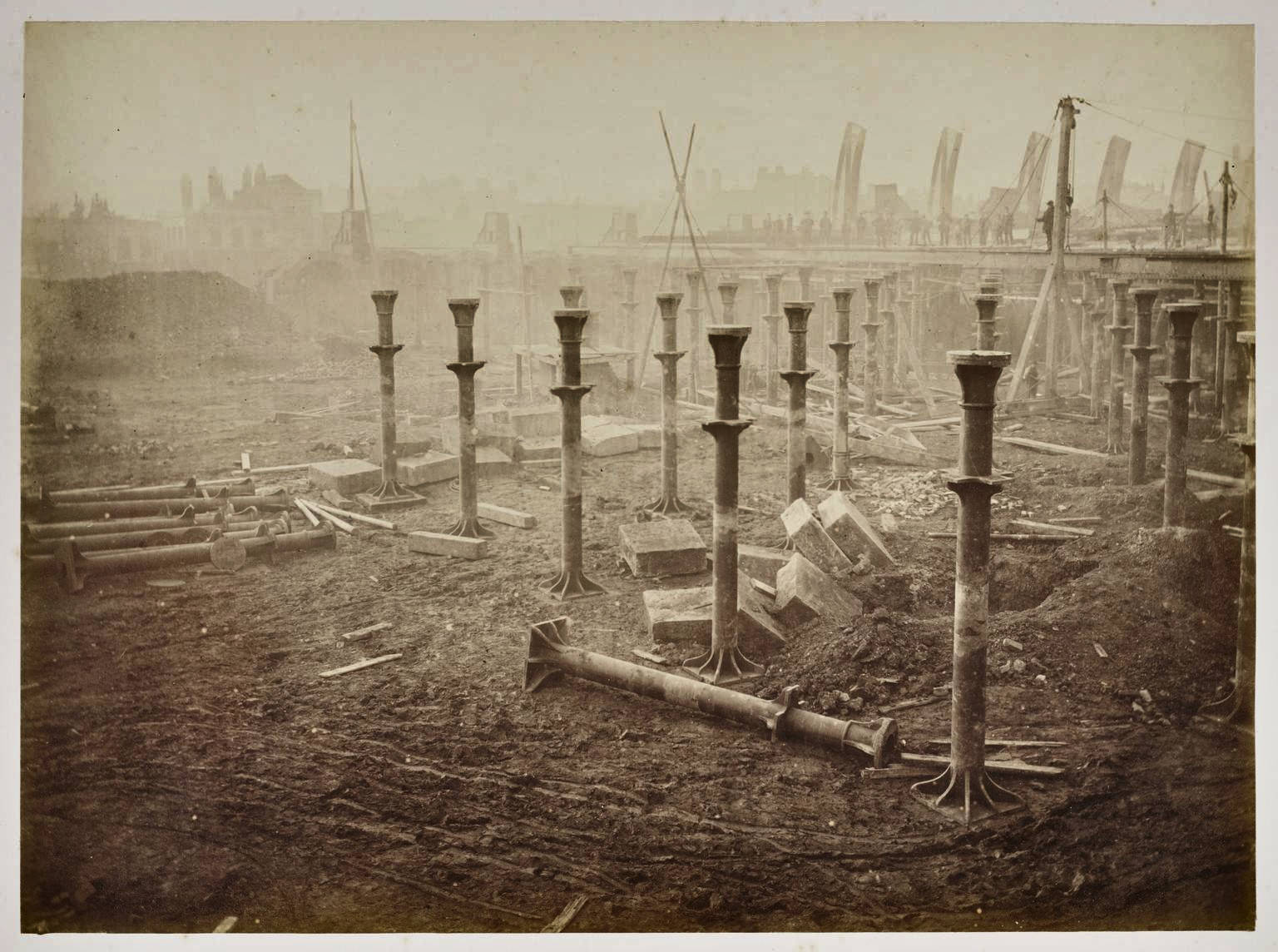
In this photograph, the upright (13" diameter) columns have already been set on their stone bases in perfectly aligned rows, ready to support the train shed floor. Other columns and stone blocks are lying haphazardly on the ground, awaiting their turn for installation. Note the wheelbarrow tracks and boot prints in the mud (foreground).
Construction of St Pancras station, about 1867.
large_1998_8759_3_6.jpg
Image 12
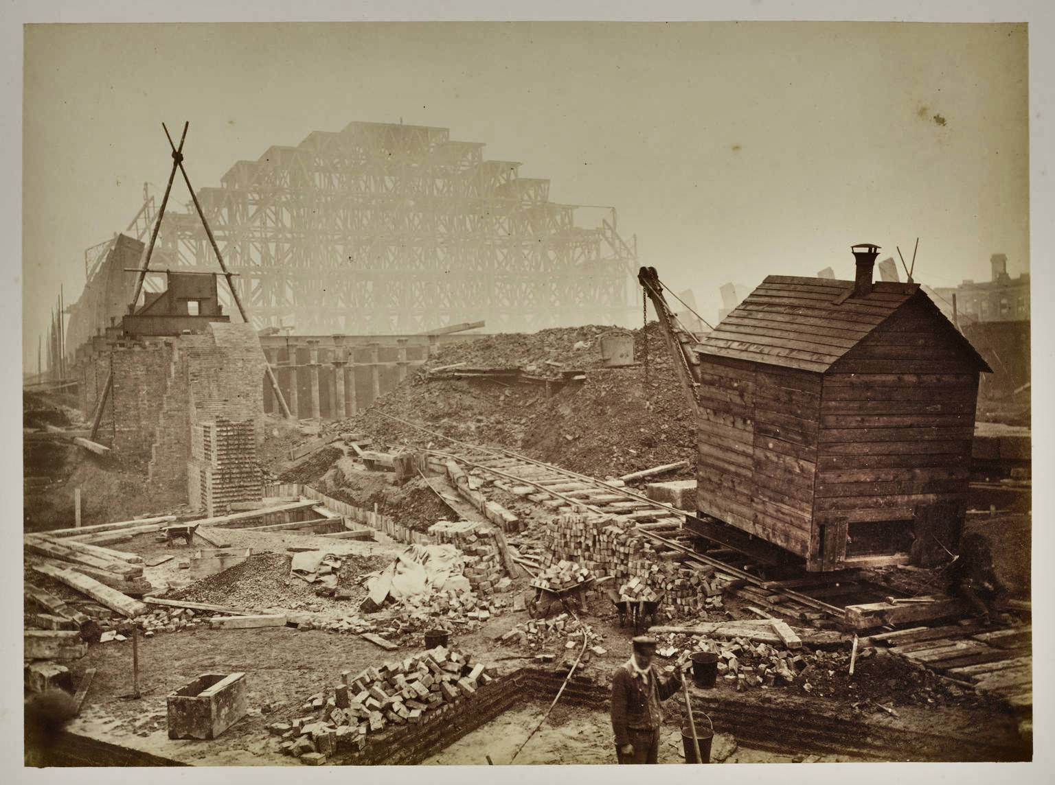
Construction of St Pancras station, about 1867.
large_1998_8759_3_9.jpg
Image 13
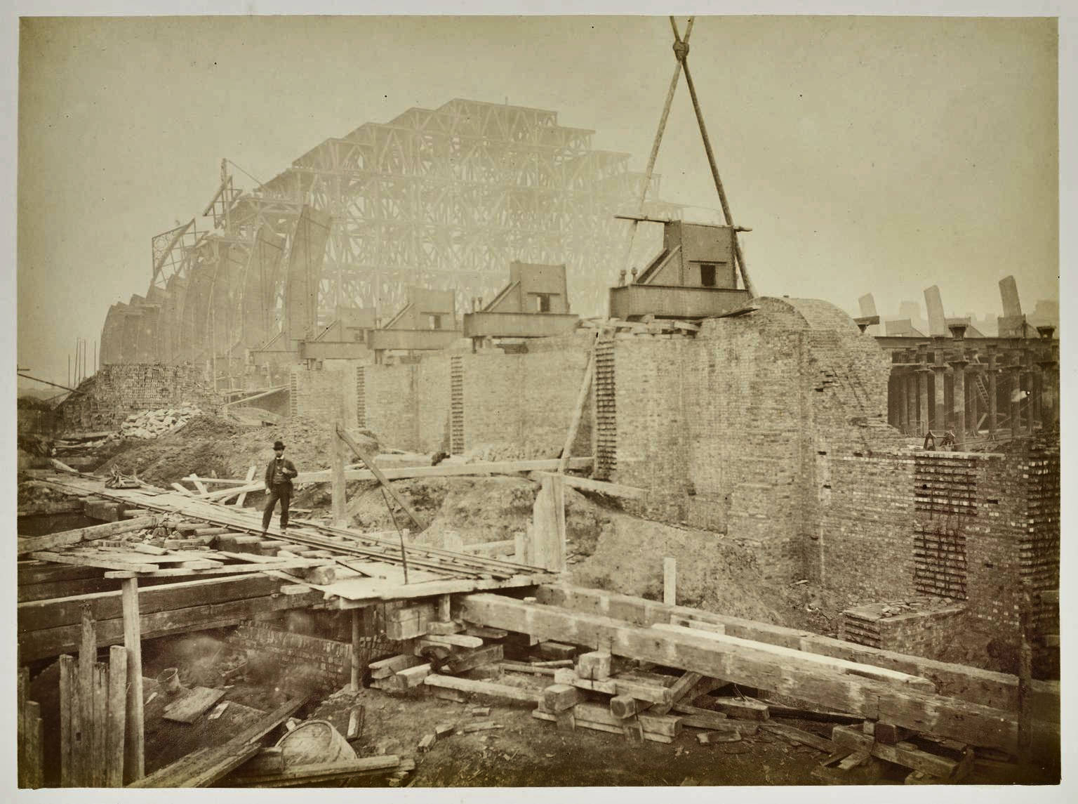
Construction of St Pancras station, about 1867.
large_1998_8759_3_7.jpg
Image 14
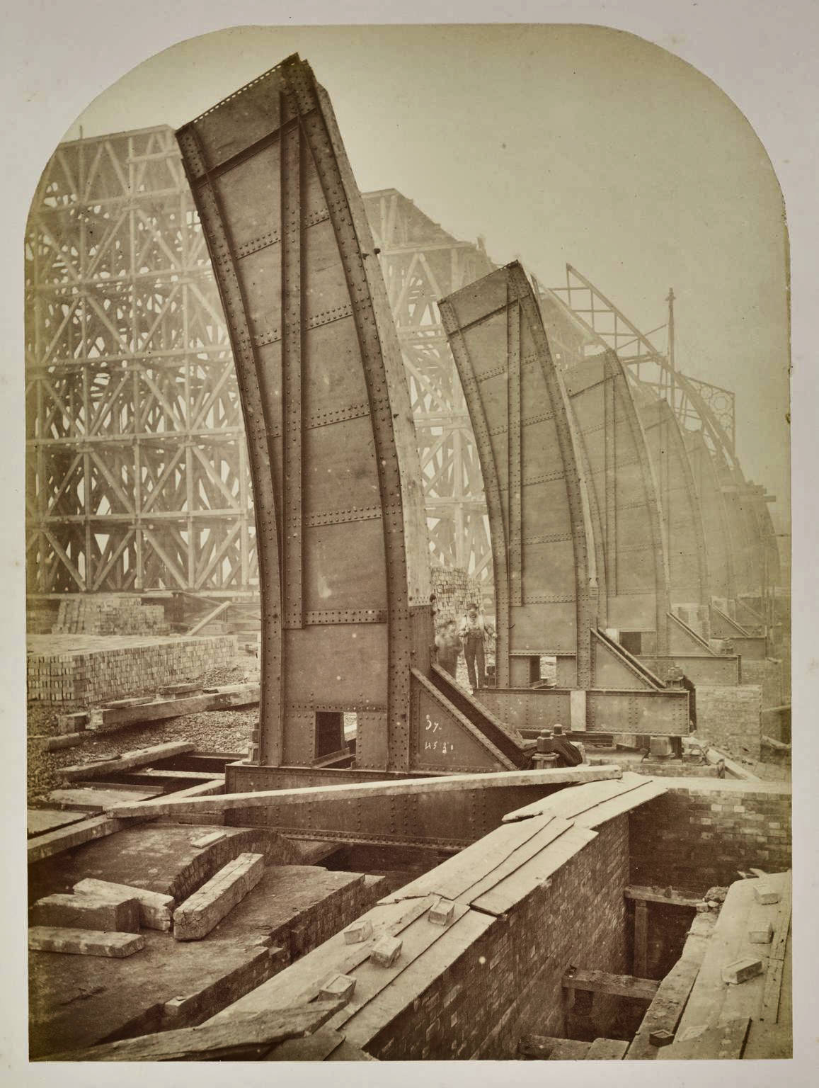
Construction of St Pancras station, about 1867.
large_1998_8759_3_10.jpg
Image 15
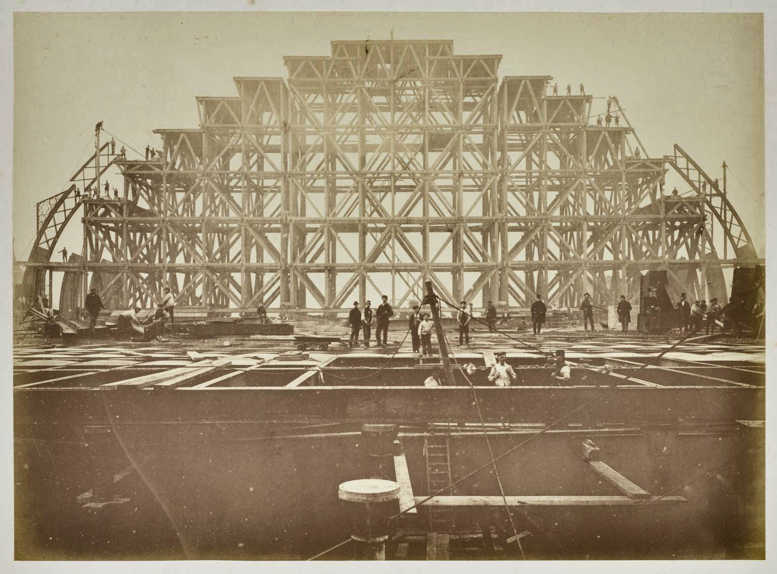
Construction of St Pancras station, about 1867.
large_1998_8759_3_8.jpg
Image 16
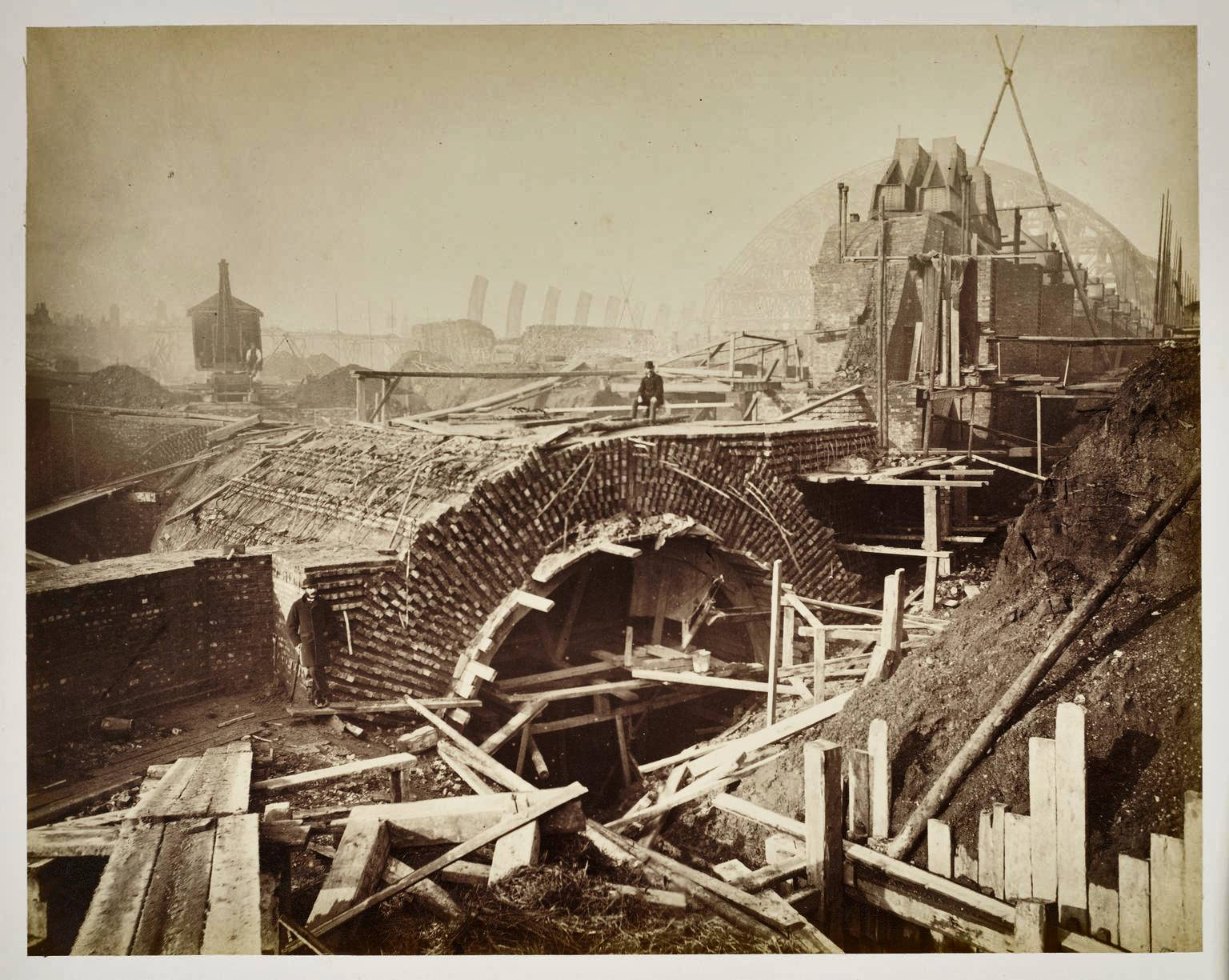
St Pancras station construction, about 1867.
large_1998_8759_3_11.jpg
Image 17
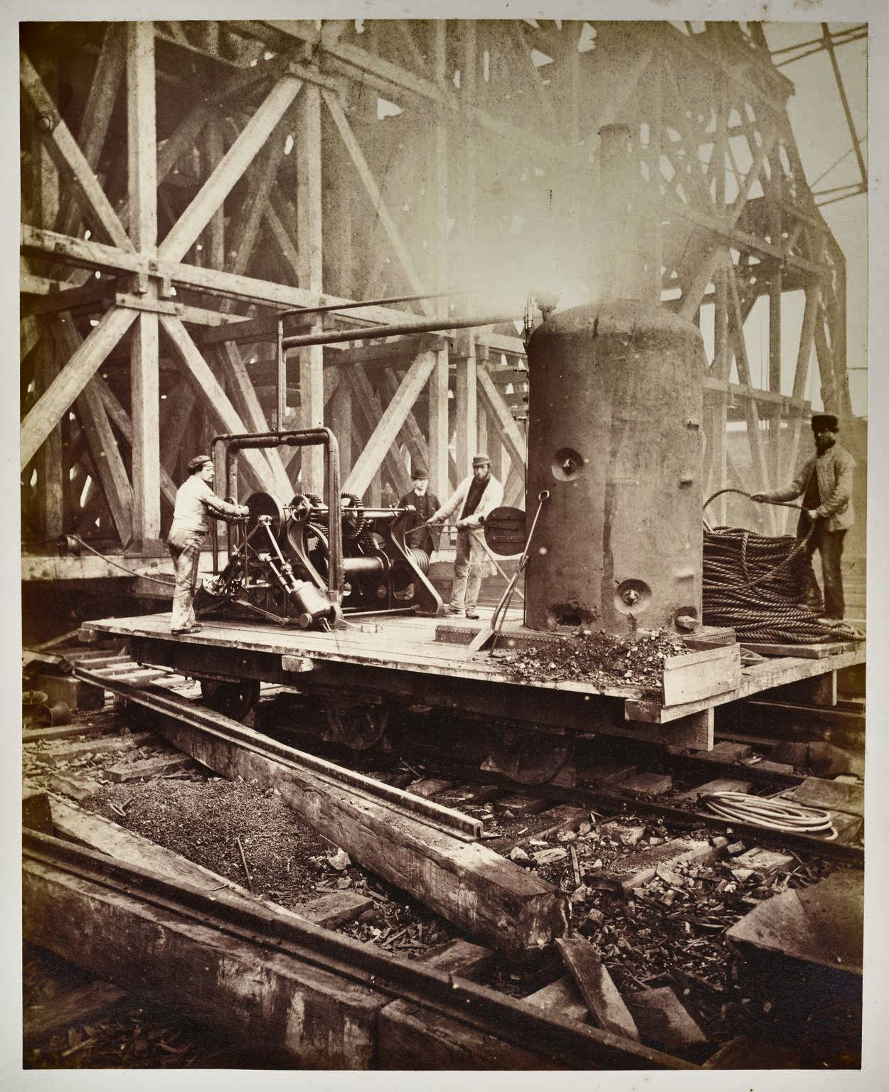
This steam-powered winch was used to lift and manoeuvre the component sections of ironwork into place so that they could be riveted together to form the ribs.
Construction of St Pancras station, about 1867.
large_1998_8759_3_13.jpg
Image 18
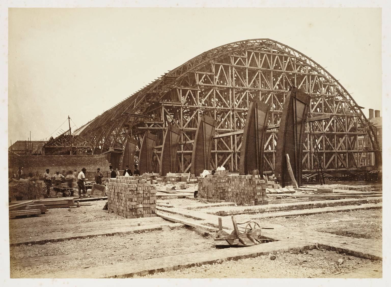
Construction of St Pancras station, 1868.
large_1998_8759_3_17.jpg
Image 19
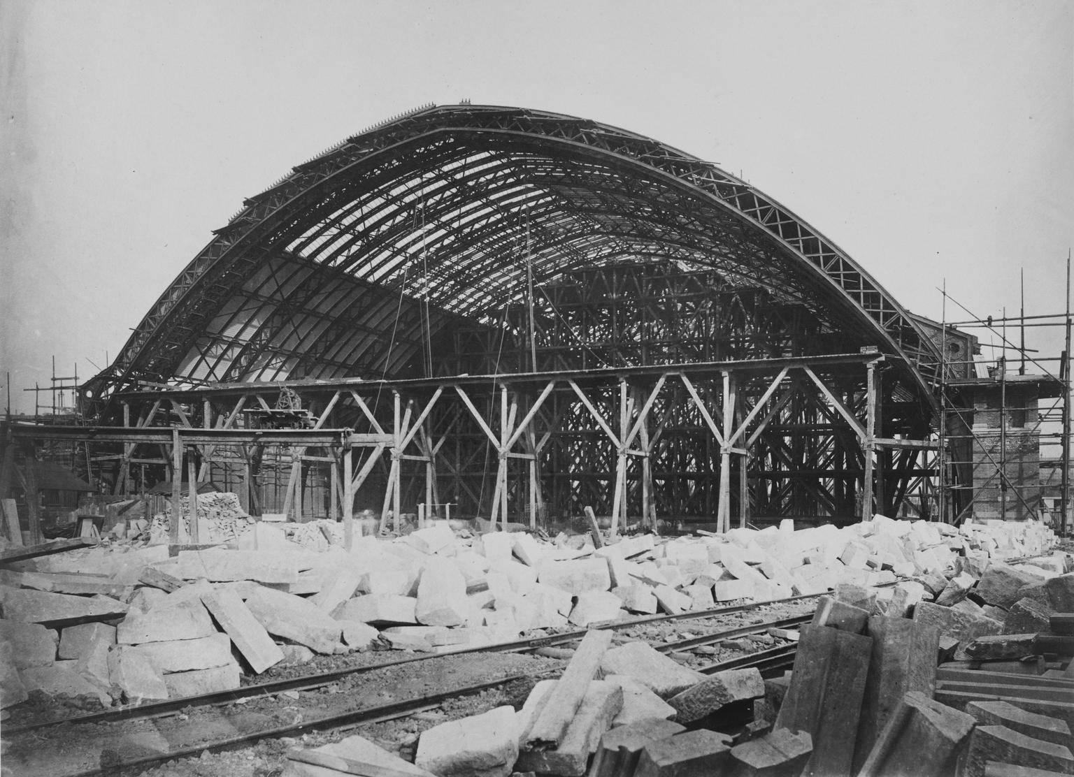
The north end of the train shed, looking south. The first section of train shed roof has already been glazed & boarded. The first of the three horizontal girders has been installed for the gable end screen and the staging is gradually moving southwards. The area in the foreground is being used as a stone yard and it appear to be served by a pair of temporary rail sidings. Note the finished stone (bottom right).
Construction of Midland Railway extension to London St Pancras, 1867-1868.
large_DS100526.jpg
Image 20
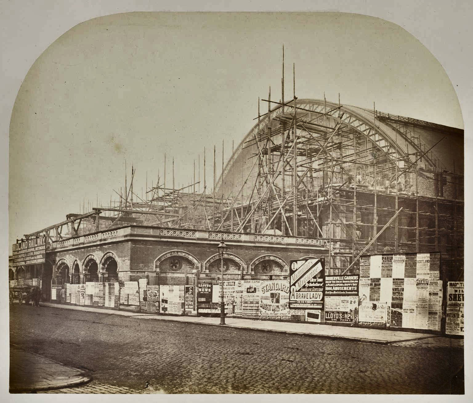
View of St Pancras station from Euston road, 1868.
large_1998_8759_3_25.jpg
Image 21
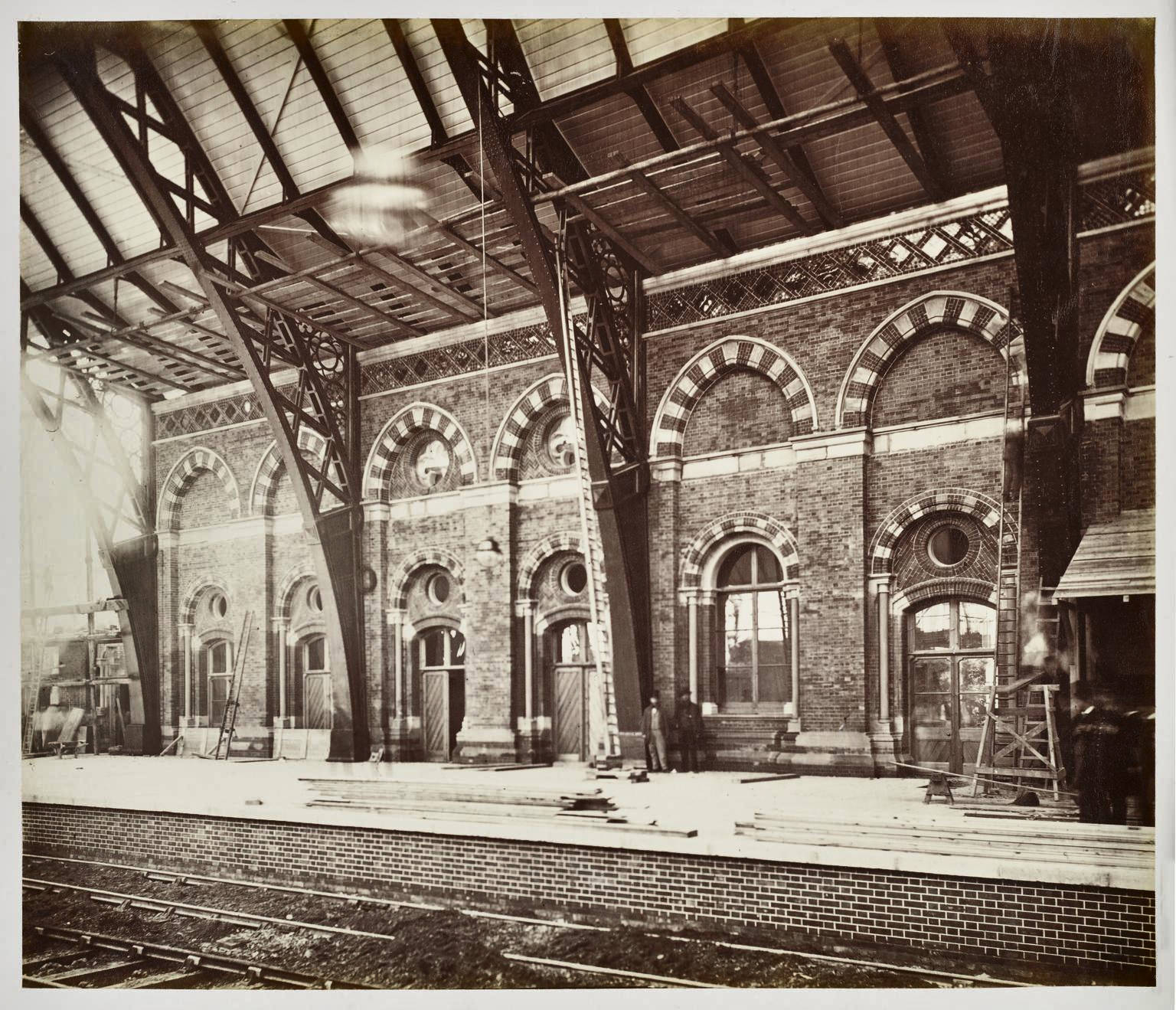
St Pancras station, 1868.
large_1998_8759_3_22.jpg
Image 22
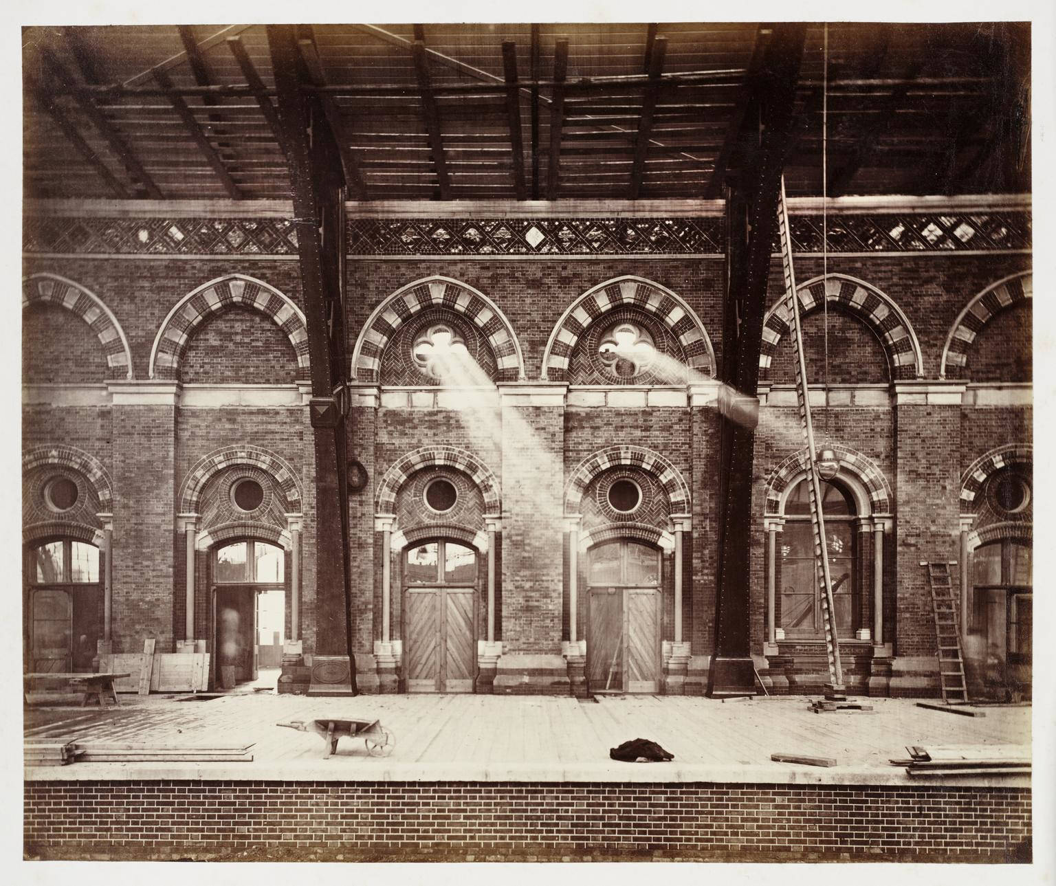
St Pancras station, 1868.
large_1998_8759_3_21.jpg
Image 23
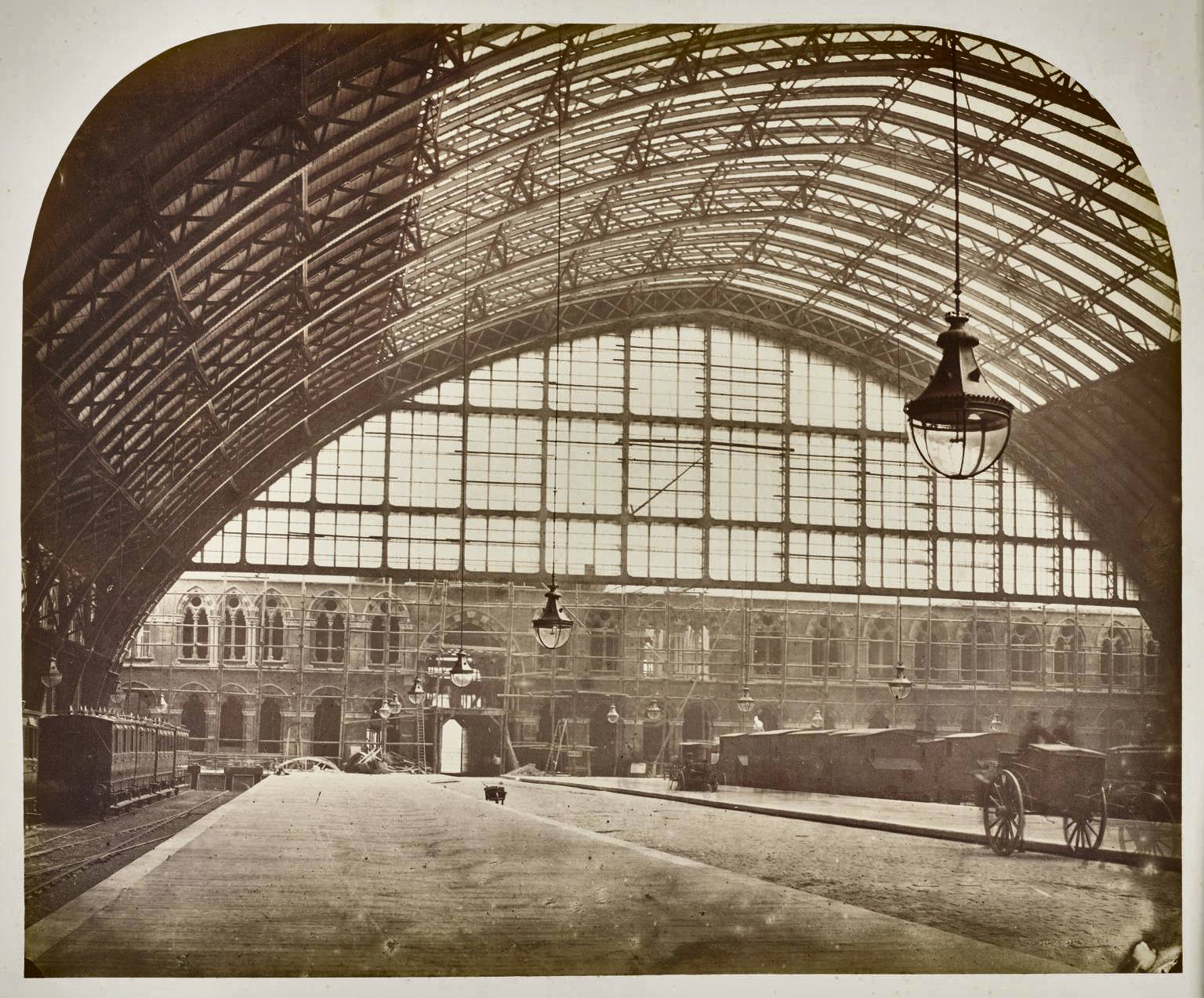
Construction of St Pancras station, 1868.
large_1998_8759_3_24.jpg
Image 24
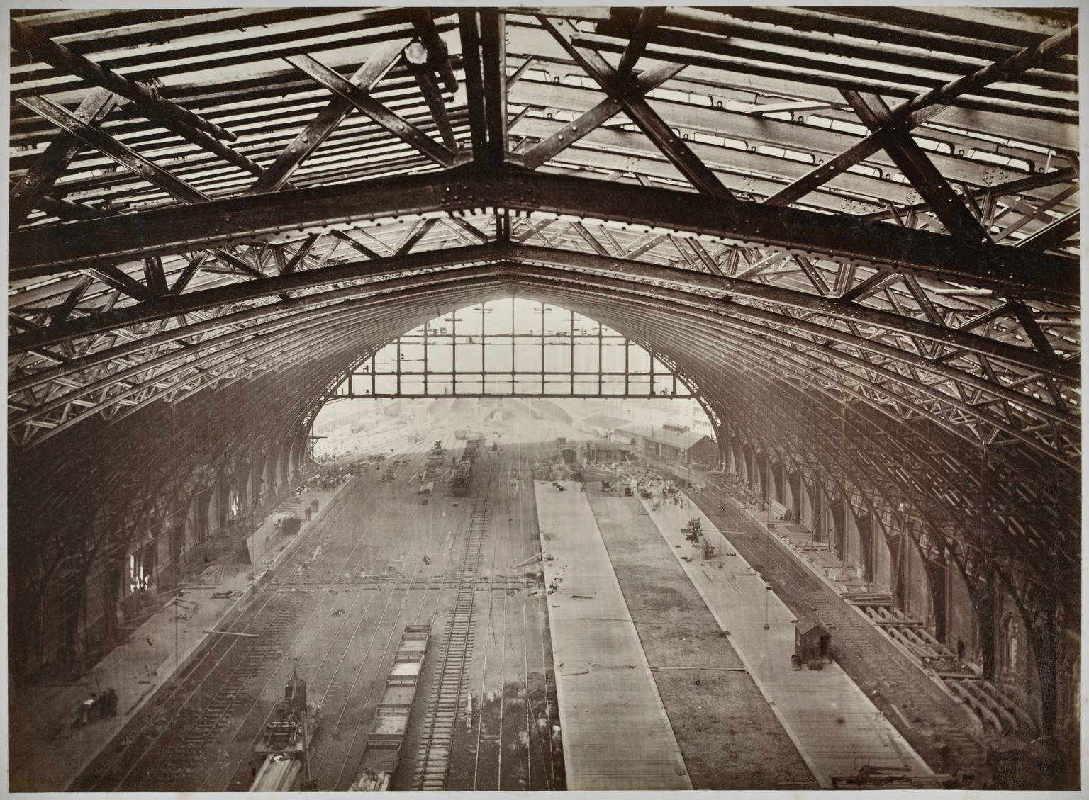
St Pancras station, view from the roof towards the platforms, 1868.
large_1998_8759_3_23.jpg
Image 25
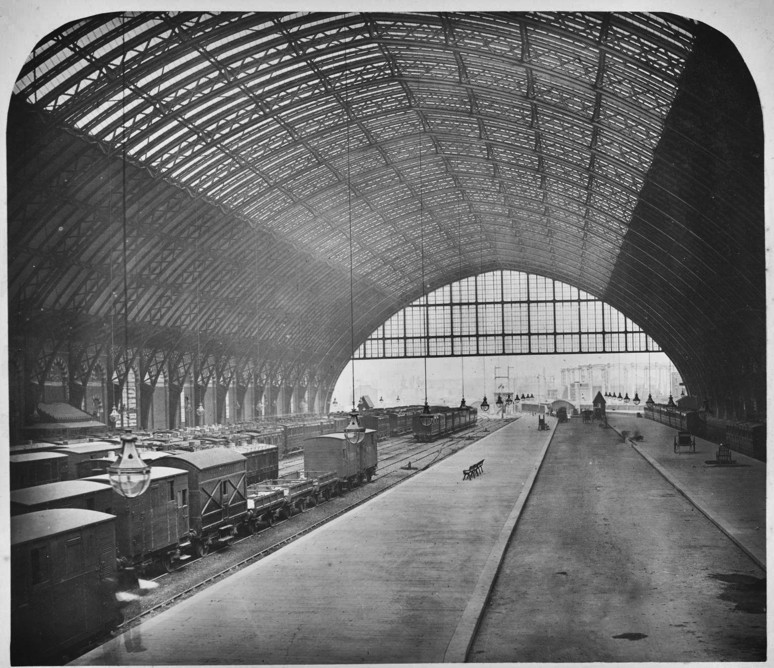
Construction of Midland Railway extension to London St Pancras, 1867-1868.
large_DS100527.jpg
The original images can be viewed at:
https://collection.sciencemuseumgroup.org.uk/objects/co442043/photographs-of-the-works-in-progress-of-the-midland-railway-photographs.
Miscellaneous
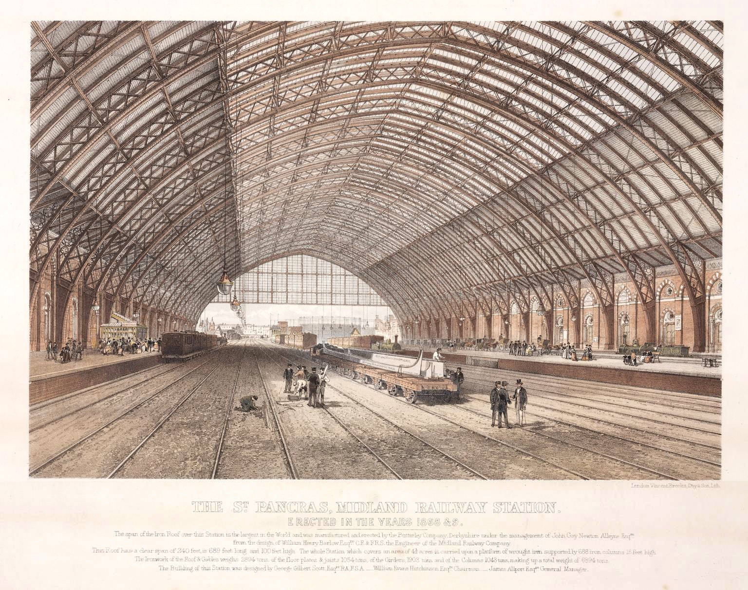
The image in this section is a coloured lithograph sourced from the Science Museum Group Collection Online on July 27, 2022 (object number 1946-303). This image has been edited to increase contrast and improve the readability of the text and it is shared under the Creative Commons Attribution-NonCommercial-ShareAlike 4.0 Licence - see
https://creativecommons.org/licenses/by-nc-sa/4.0.
The original image can be viewed at:
https://collection.sciencemuseumgroup.org.uk/objects/co66093/coloured-lithograph-st-pancras-station-print.
Derby Works Collection
The images in this section are photographs sourced from the Science Museum Group Collection Online on July 27, 2022 (collection reference 1997-7397). All of these images have been edited to increase contrast, reduce the glare introduced during the digitisation process and thereby significantly increase the amount of visible detail and they are shared under the Creative Commons Attribution-NonCommercial-ShareAlike 4.0 Licence - see
https://creativecommons.org/licenses/by-nc-sa/4.0.
The original images can be viewed at:
https://collection.sciencemuseumgroup.org.uk/objects/co423004/derby-works-collection-collection-of-photographs.
London Midland & Scottish Railway Collection
The images in this section are photographs sourced from the Science Museum Group Collection Online on July 27, 2022 (collection reference 1997-7409). All of these images have been edited to increase contrast, reduce the glare introduced during the digitisation process and thereby significantly increase the amount of visible detail and they are shared under the Creative Commons Attribution-NonCommercial-ShareAlike 4.0 Licence - see
https://creativecommons.org/licenses/by-nc-sa/4.0.
The original images can be viewed at:
https://collection.sciencemuseumgroup.org.uk/objects/co423016/london-midland-scottish-railway-collection-collection-of-photographs.
Images from other sources
Image 32a
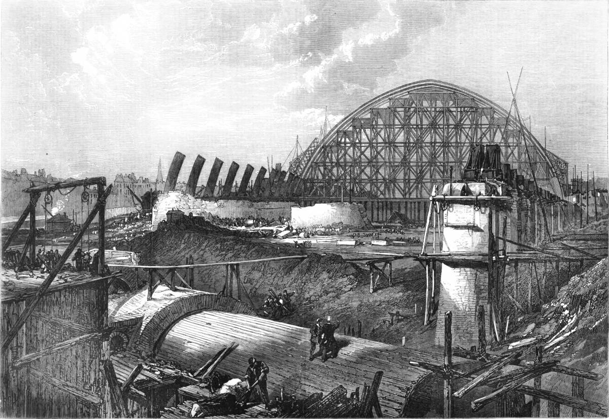
'Works of the Midland Railway Terminus, Euston Road.'
A full-page illustration from page 160 of the Illustrated London News dated Feb, 15, 1868.
Public Domain.
Compare this with Images 16, 20 & 27.
Image 33
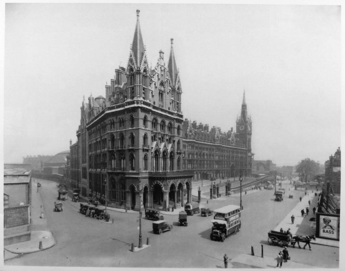
Courtesy of the Midland Railway Study Centre, Derby (item number 61966).
This version has been desaturated (to remove a yellow colour cast) and resized.[**]
61966.jpg
https://creativecommons.org/licenses/by-nc-sa/4.0.
The original versions can be accessed by searching for the item number in the MRSC catalogue at https://www.midlandrailwaystudycentre.org.uk/catalogue.php.
Further reading
[A] For a very brief history of the station, including a scale drawing showing a cross-section through the train shed roof, see "The history of London St Pancras International station" at:
https://www.networkrail.co.uk/who-we-are/our-history/iconic-infrastructure/the-history-of-london-st-pancras-international-station/
[B] For a slightly more detailed history of the station's construction and the role of George Gilbert Scott, see "The Construction of St Pancras" at:
https://gilbertscott.org/the-construction-of-st-pancras/
[C] For a comprehensive first-hand account of the planning and construction process (with reduced-size reproductions of scale drawings), plus a review of the costs, see the "Description of the St Pancras Station and Roof, Midland Railway" by William Henry Barlow, F.R.S., M.Inst.C.E. (the Midland Railway Company's consulting engineer). This paper also explains why the ironwork of the train shed roof was (and still is) painted blue. A short extract from this paper has been reproduced in footnote 1 below. A digital version of the full paper (dated March 29, 1870) can be downloaded from the online catalogue of the Midland Railway Study Centre by searching for Item Number: 21696 at: https://www.midlandrailwaystudycentre.org.uk/catalogue.php
[D] For a set of 33 architectural and engineering drawings relating to the construction of St. Pancras station and its approaches, see the "Drawings of the Midland Railway Extension to London (St Pancras)" collection at:
https://collection.sciencemuseumgroup.org.uk/documents/aa110002831/drawings-of-the-midland-railway-extension-to-london-st-pancras
[E] For a description of the interior of the Grand Hotel shortly before its opening, see pages 345-349 of "The Midland railway: its rise and progress. A narrative of modern enterprise" by Frederick Smeeton Williams, published by Strahan & Co London in 1876. Also, pages 332-345 provide a slightly verbose, but nonetheless interesting description of the station works (some of which will seem remarkably familiar if you've read Barlow's account [C]). A 42Mb pdf version of Williams' book can be downloaded from:
http://www.archive.org/details/midlandrailwayit00will.
[F] For photographs and information relating to the construction of the line to the north of the station, see section 'B: Bedford to London' in the companion article entitled 'Building railways in the 1860s: two Midland extensions'.
Footnotes & Acknowledgements
[1] In a paper presented to the Institution of Civil Engineers on 29 March 1870 [C], the Midland Railway Company's consulting engineer W.H. Barlow provides the following description of the train shed roof and the process that enabled it to be constructed so quickly. The relevant section has been transcribed in full and reproduced below as it significantly aids the interpretation of the construction-era photographs.
Description of the lower floor.
The lower floor contains seven hundred and twenty cast-iron columns set with stone bases on brick piers. There are forty-nine rows of principle girders across the station, and fifteen similar girders running longitudinally. These carry intermediate girders, and the whole is covered with Mallet's buckle-plates. The strength of the girders and plating is sufficient to carry locomotives all over the floor, of which the cost of the ironwork was £57,000, or nearly £3 0s. 6d. per square yard.Description of the roof
The main ribs or principles are made of channel-iron and plate-iron, and are 6-feet deep, or one-fortieth of the clear span. The rib between the walls is of open work, but the extremities of the principles in the walls are of solid plates. ... the total weight of each rib is 54 Tons, 64 cwt. ... The cost of each rib is ... £1,132 4s. 0d.The ribs project in front of the piers of the walls, and the piers project from the line of the wall. The width, measured between the walls, is 245 feet 6 inches and the distance from centre to centre of the ribs is 29 feet 4 inches. The arch is slightly pointed at the crown, as this form apparently posses some advantages in resisting the lateral action of wind, while it improves the architectural effect. The radius of curvature was diminished at the haunches, to give increased head room near the walls. ... The glazing is ridge and furrow, ventilation being obtained along the whole length of each ridge, which is left open and protected from wet by a ventilator cover: the ventilation is thus very complete. The roof is also provided with gangways throughout so that any pane of glass can be taken out and replaced. The gable ends or screens consist of three horizontal lattice girders, 6 feet wide, united and carried by verticals of similar construction.
... The erection of the roof was effected by two large timber stages, each made in three divisions, so that each part of either stage could be moved separately. These stages were designed by the Butterley Company, who were the contractors for the roofing and for the lower floor, Mr. (now Sir) G.J.N. Alleyne being the manager. The stages were 40 feet in width, of great strength and solidity, and contained about 25,000 cubic feet of timber and 80 tons of ironwork. The weight of each stage was about 580 tons, and with two ribs on it, the weight on the floor-girders where it stood, including men and apparatus, was about 650 tons. The passage of these stages, which moved on wheels, along the floor of the building, constituted a good test of the strength of that portion of the work.
The process of erecting was as follows; the two lower portions or the feet of the ribs were first set temporarily in position, the brickwork underneath them being kept about 3 feet below its intended height. The feet were then accurately adjusted by timber-packing and wedges, and riveted to the ends of the floor girders; after which the brickwork was carried up in blue Staffordshire bricks set in Portland cement, and the whole secured to the underside of the ironwork, the timber packings being removed as the work proceeded.
The open work of the main ribs was commenced from the extremities on each side, in divisions of about 18 feet in length, and these were placed temporarily together, supported by the staging, until all the pieces were in position. The whole was then adjusted for line and level, and riveted together with the purlins and other ironwork.
The time required for putting up the pieces and riveting, after the feet were fixed, was six days for each rib, and the last fourteen principles were erected in seventeen weeks, including delays from weather, and occasionally failure in the supply of materials and other causes. The ironwork was lifted by an ingeniously contrived engine, which worked ropes to derricks placed on the stages. The supports were adjustable on the stage. Special arrangements were employed to secure the line, form, and level of the work; and, the whole of the ironwork having been fitted at the Butterley Works, it was put together without difficulty. The greatest depression of any rib when the centre was struck was only 1/4 of an inch, and the average was 3/16 of an inch.
The contract provided for testing the roof; but the extreme stiffness of the work, and the unavoidable tests to which it was from time to time subjected during erection, were sufficient to show that no formal testing was necessary. In consequence of a delay in obtaining face-bricks for the side walls, a considerable number of ribs were erected, boarded, slated, and glazed before the side walls were built, and in that state the roof endured several gales of wind, one of which was unusually heavy, without the slightest visible movement. The lines of the roof are remarkably well preserved.
The Butterley Company are entitled to great credit for the manner in which the roof has been constructed, and their managing foreman on the works, Mr. Clark, is deserving of special mention, for erecting the work and putting it together on the ground.
This article was conceived, researched and written by Mark R. Harvey. © Mark R. Harvey (2022), except where otherwise indicated / credited.

