The document takes the form of a single sheet with slightly eroded edges and it appears to have been mounted onto art board or similar (perhaps as part of a conservation process).[1] The sheet contains a partly colour-washed set of scale drawings that depict the stone version of the standard Midland Railway Company design for the 'Number 2' or 'Medium' main station buildings (booking offices) on its Settle and Carlisle Railway.
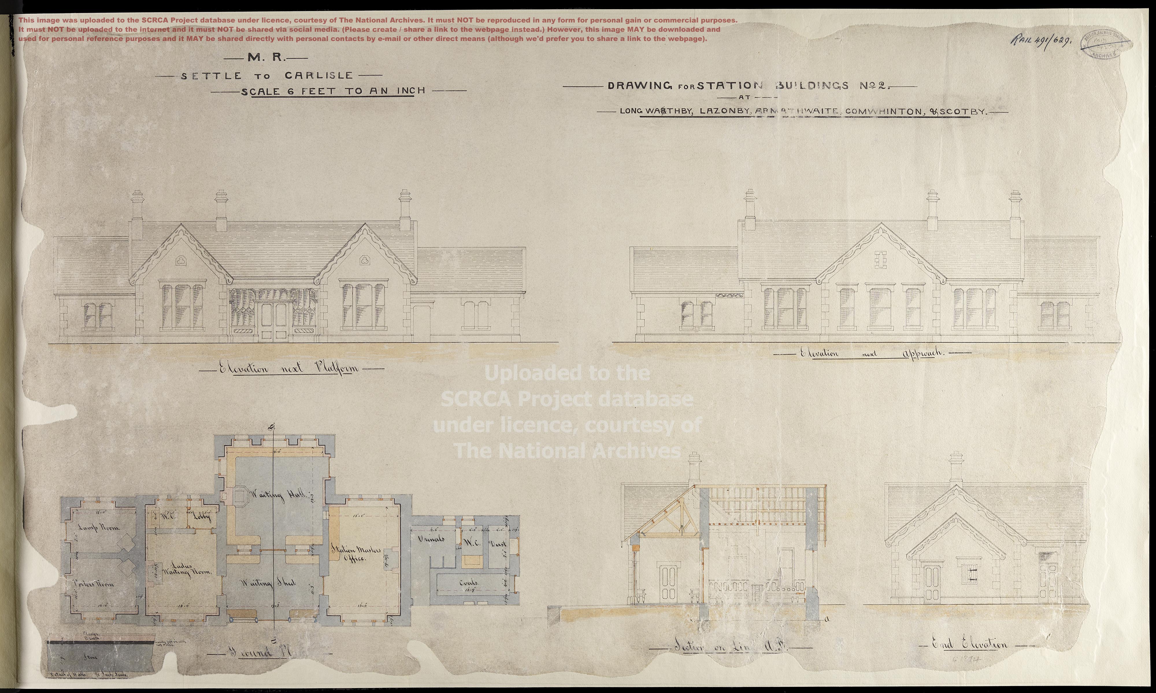
Tip: To open a larger version of this image (4,000 x 2,401 pixels, 1.4Mb), click / tap on the thumbnail above.
The image above has been uploaded to the SCRCA Project database under licence, courtesy of The National Archives. It must NOT be reproduced in any form for personal gain or commercIal purposes. It must NOT be uploaded to the internet and it must NOT be shared via social media. (Please create / share a link to this webpage instead.) However, it MAY be downloaded and used for personal reference purposes and it MAY be shared directly with personal contacts by e-mail or other direct means (although we'd prefer you to share a link to this webpage).
The larger version will repay close examination and the following are especially worthy of note:
- The sheet has two separate title blocks. At top left: "M.R. SETTLE TO CARLISLE". At top right: "DRAWING FOR STATION BUILDINGS No2. AT LONGWA
RTHBY", LAZONBY, ARMATHWAITE, COMWHINTON, & SCOTBY. Note the 'R' in Longwarthby. This has been crossed-out on the drawing. Note too the use of the letter 'O' rather than 'U' at the beginning of Comwhinton. This has not been altered on the drawing. - The drawing is undated, but it almost certainly formed part of the contract documentation and / or the working documentation associated with the construction of the Settle and Carlisle Railway between 1869 and 1876.
- The drawing does not include any mention of the engineer or architect.
- The scale is given as "6 FEET TO AN INCH" (indicated by original text) and it is clear that the original was drawn to scale.
- The sheet includes six separate but related drawings. They are labelled "Elevation next Platform", "Elevation next Approach", "Ground Plan", "Section on Line a.b.", "End Elevation" and "Detail of Walls".
- "Line a.b." is mentioned in the label for one of the drawings and this is depicted on the "Ground Plan" as a transect through the platform edge, the "Waiting Shed" and the "Waiting Hall".
- With the exception of the "Waiting Shed" frontage, the elevation views do not indicate the nature of the materials to be used for the exterior walls. Stone sills, lintels wall angle quoins are clearly depicted and the "Waiting Shed" is depicted with decorative columns, bracketry, glazing and timber pannelling.
- All elevation views depict the pitched roofs as being covered with slates and topped with plain ridge tiles.
- The elevation views depict pierced decorative timber bargeboards on all gable ends.
- Five fireplaces and three decorative chimney stacks are depicted, but chimney pots are not depicted.
- The "Ground Plan" and "Section on Line a.b." views depict the exterior walls as follows:
- double-skinned for the main part of the building (stone outside, brick inside)[2] and
- single-skinned for the utility block.
- The elevation views depict a trefoil oculus in each of the platform-facing upper gables and a vertical recess in the upper gable facing the approach road.
- The plan view shows the interior divided into eleven rooms (twelve if you count the W.C.s and their lobbies separately).
- The dimensions are given in feet & inches and the focus is placed firmly on the room interiors and the wall thicknesses.
- The key dimensions (indicated on the plan view by text and accompanying arrows) are slightly different to the brick version and are as follows:
- Main building:
- "Lamp Room" (12' 0" wide x 8' 0" deep) with a corner fireplace, a window facing the approach road and an external doorway to the left side.
- "Porters Room" (12' 0" wide x 10' 0" deep) with a corner fireplace, a window facing the platform and an external doorway to the left side.
- "Ladies Waiting Room" (13' 0" wide x 14' 10½" deep) with a central fireplace, a window facing the platform, an internal doorway leading to the waiting shed and an internal doorway leading to...
- "Lobby" (5' 0" wide) with wash basin and an internal doorway leading to "W.C." (7' 6" wide x 4' 0" deep), each with a window facing the approach road.
- "Waiting Shed" (17' 3" wide x 11' 3" deep) with a pair of windows facing the platform either side of an external doorway to the platform and an internal doorway leading to...
- "Waiting Hall" (18' 0" wide x 18' 3" deep) with a central fireplace, windows in two sides (facing the approach road and looking along rear) an external doorway to the right side and a ticket window (unlabelled) linking to...
- "Station Masters Office" (13' 0" wide x 19' 10½" deep) with a central fireplace, a window facing the approach road, a window facing the platform and an internal doorway leading to the "Waiting Shed".
- Utility block:
- "Urinals" (8' 6" wide) - without wash basin but with a window facing the approach road and an internal doorway leading to....
- "W.C." (4' 0" wide) with a window facing the approach road.
- "Dust" (4' 0" wide x 8' 0" deep) with a hatch to the right side (but no doorway, either internal or external).
- "Coals" (13' 9" wide x 4' 0" deep) with a window facing the platform and an external door to the right side
- Main building:
- On the plan view:
- The stonework element of all external walls is labelled as 1' 9" thick.
- Major interior walls are depicted as being stone only and are labelled as 1' 9" thick.
- Minor interior walls are depicted as being stone only and are labelled as 1' 0" thick.
- External dimensions are not provided, but they can be calculated by totalling-up the dimensions that are provided on the plan.
- The plan view shows bench seating along the three sides of the "Waiting Hall" and two sides of the "Waiting Shed".
Notes
[1]: This review was created from the digital image file supplied by the National Archives. The reviewer has not seen the original document, so cannot be certain of its physical nature.
[2]: This is confirmed and clarified by the "Detail of Walls" drawing (bottom-left). This an enlargement, showing a cross-section through the thickness of a wall at "½ Inch Scale." It depicts the following:
- "Stone" with a dimension of 1' 9"
- "Cavity fill in with hot pitch" with a dimension of ½"
- "Brick" with a dimension of 2 x 4"
- "Plaster" (no dimension given)
It is interesting to speculate if the pitch was added in reality. If not, or if it was done poorly, or if was done but has since deteriorated, it would explain the water ingress problems that have affected several of the main station buildings.
Acknowledgements
This drawing forms part of a large set of records of "the privately owned railway companies (and their predecessors) taken over by the British Transport Commission under the Transport Act 1947". This digitised version of the drawing was uploaded to the SCRCA Project database under licence, courtesy of The National Archives. (Catalogue Reference RAIL 491/629, Harbour Contract drawings: Station buildings on Settle - Carlisle line.) The license was purchased by - and is held by - Mark R. Harvey.
Review and text by Mark R. Harvey (© Mark R. Harvey, 2020).