The document takes the form of a single sheet with severely eroded edges and it appears to have been mounted onto art board or similar (perhaps as part of a conservation process).[1] The sheet contains a partly colour-washed set of scale drawings that depict the stone version of the standard Midland Railway Company design for stand-alone waiting rooms on its Settle and Carlisle Railway (see SCRCA Location Variant: Station Waiting Room - MRC SCR Standard).
Tip: To open a larger version of this image (2,000 x 1,452 pixels, 449Kb), click / tap on the thumbnail above.
The image above has been uploaded to the SCRCA Project database under licence, courtesy of The National Archives. It must NOT be reproduced in any form for personal gain or commercIal purposes. It must NOT be uploaded to the internet and it must NOT be shared via social media. (Please create / share a link to this webpage instead.) However, it MAY be downloaded and used for personal reference purposes and it MAY be shared directly with personal contacts by e-mail or other direct means (although we'd prefer you to share a link to this webpage).
The larger version will repay close examination and the following are especially worthy of note:
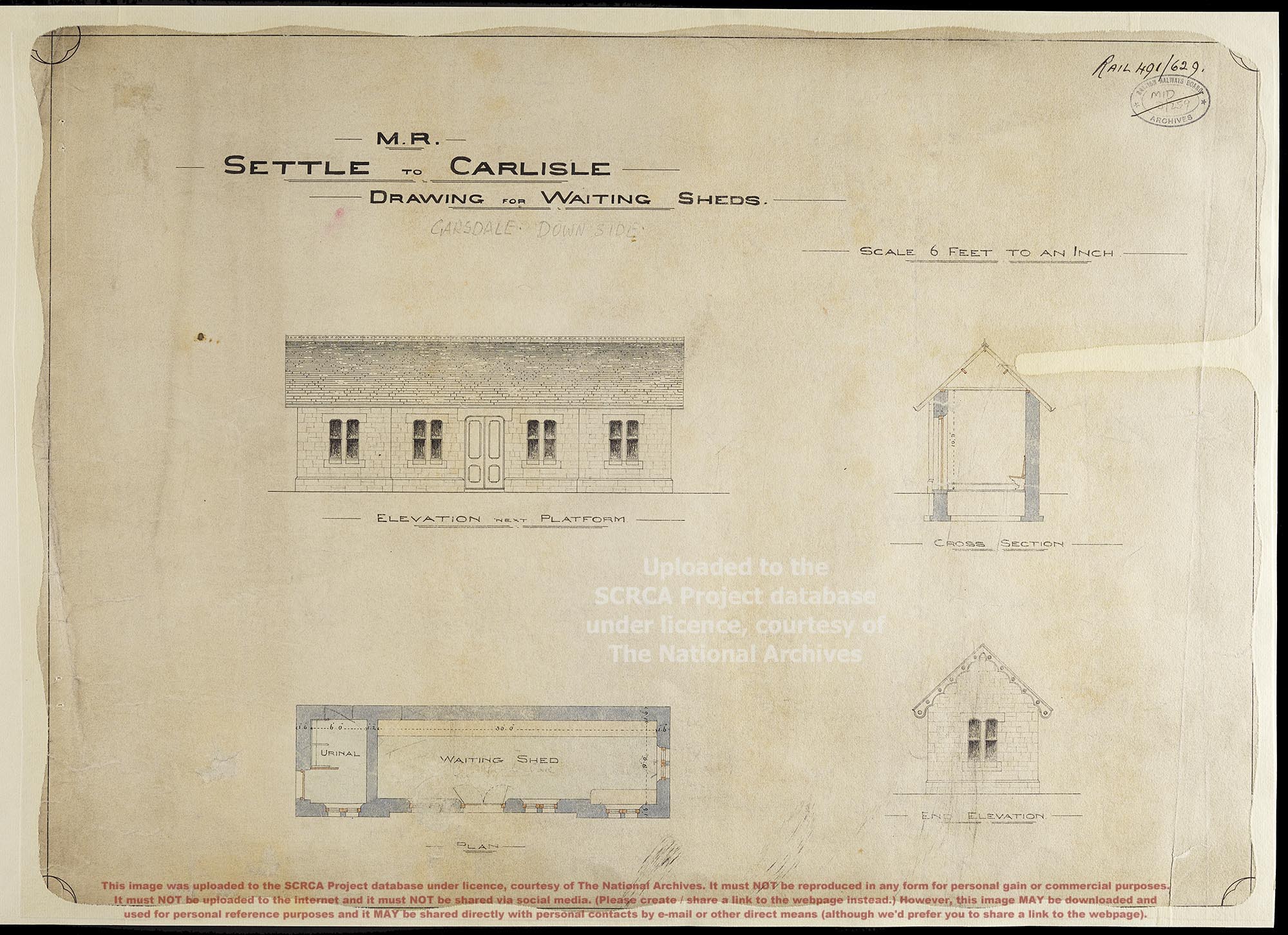
- The title on the drawing (top-left) is "M.R. SETTLE TO CARLISLE. DRAWING FOR WAITING SHEDS.".
- Immediately below the title is an annotation in pencil that reads "GARSDALE DOWN SIDE".
- The drawing is undated, but it almost certainly formed part of the contract documentation and / or the working documentation associated with the construction of the Settle and Carlisle Railway between 1869 and 1876.
- The drawing does not include any mention of the engineer or architect.
- The scale is given as "6 Feet to 1 Inch" (indicated by original text) and it is clear that the original was drawn to scale.
- The sheet includes four separate but related drawings. They are labelled "ELEVATION NEXT PLATFORM", "CROSS SECTION", "PLAN" and "END ELEVATION".
- The elevation views depict the exterior walls as stone (rather than brick) and the plan view depicts the exterior walls as being single-skinned.[2]
- The "ELEVATION NEXT PLATFORM" view depicts the pitched roof as being covered with slates and topped with decorative (pierced) ridge tiles.
- The "END ELEVATION" view depicts pierced decorative timber bargeboards on the gable end.
- No chimneys or fireplaces are depicted.
- The plan view shows the interior divided into two rooms:
- A small room labelled "URINAL" (accessed via a door in the left gable end wall, lit by a single window in the front wall).
- A larger room labelled "WAITING SHED" (accessed via a double door in the front wall, lit by four windows in the front wall and a single window in the right gable end wall).
- The plan view also shows bench seating along the full length of the rear wall of the "WAITING SHED" room and along approximately half of the length of the front (platform-facing) wall of the "WAITING SHED" room (in the corner, to the right of the double door).
- The dimensions are given in feet & inches and the focus is placed firmly on the room interiors and the wall thicknesses. External dimensions are not provided (so must be calculated).[3] The key dimensions (indicated by text and accompanying arrows) are:
- exterior wall thickness: 1' 6"
- interior wall thickness (dividing urinal from waiting shed): 1' 2"
- interior depth (front to back) throughout: 9' 0"
- interior width of urinal: 6' 0"
- interior width of waiting shed: 30' 0"
- interior height (floor to ceiling): 10' 9"
Notes
[1]: This review was created from the digital image file supplied by the National Archives. The reviewer has not seen the original document, so cannot be certain of its physical nature.
[2]: The waiting room at Armathwaite was built like this (a fact that can be easily verified because the interior has been left unplastered following its refurbishment - see Armathwaite Station Waiting Room: Interior view (looking south-west).
[3]: Approximate measurements taken on site by SCRCA Project volunteers suggest that the 'as built' dimensions of these structures do vary slightly from the standard dimensions.
Acknowledgements
This drawing forms part of a large set of records of "the privately owned railway companies (and their predecessors) taken over by the British Transport Commission under the Transport Act 1947". This digitised version of the drawing was uploaded to the SCRCA Project database under licence, courtesy of The National Archives. (Catalogue Reference RAIL 491/629, Harbour Contract drawings: Station buildings on Settle - Carlisle line.) The license was purchased by - and is held by - Mark R. Harvey.
Review and text by Mark R. Harvey (© Mark R. Harvey, 2020).