The document takes the form of a single sheet with a slightly eroded left-hand edge, most of which has been cropped-off to tidy-up and reduce the size of the uploaded version. (No important information was lost as a result of this cropping.)
Tip: To open a larger version of this image (6,000 x 4,000 pixels, 2.8Mb), click / tap on the thumbnail above.
The larger version will repay close examination and the following are especially worthy of note:
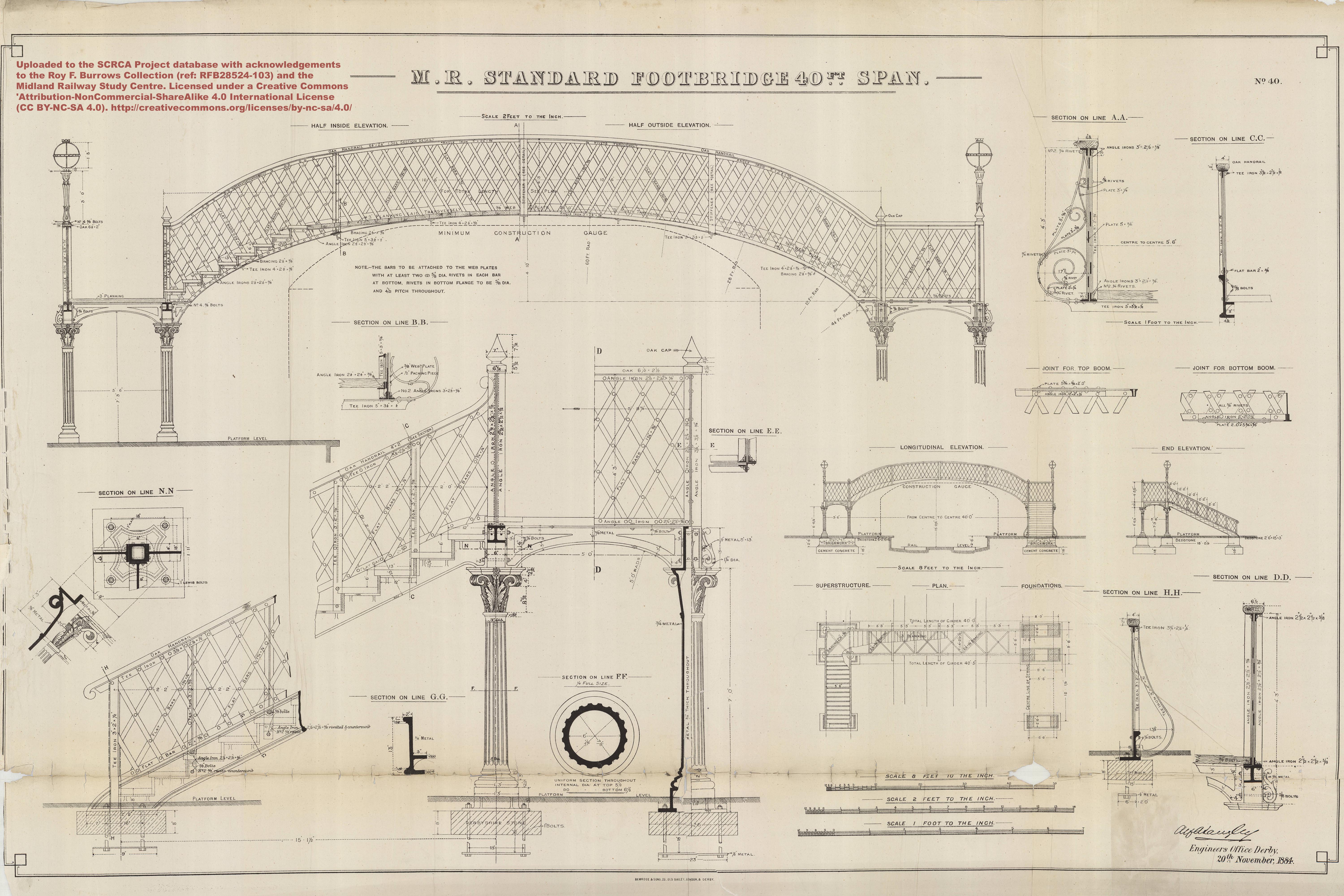
- The title on the drawing (top-centre) is "M.R. Standard Footbridge 40ft Span."
- The drawing was printed by "BEMROSE & SONS. 23. OLD BAILEY. LONDON. & DERBY." and it is signed by Alfred Langley. The text "Engineers Office Derby. 20th November 1884" follows immediately below the signature.
- The sheet includes three different drawn and stated scales: "8 FEET TO THE INCH", "2 FEET TO THE INCH" and "1 FOOT TO THE INCH".
- The sheet contains a set of eighteen distinct but related drawings, each produced at one of these scales (to best suit the subject). Collectively, these drawings depict the overall form and fine details of one variant of a Midland Railway Company standard design for a 40 foot span lattice girder footbridge intended for platform mounting and spanning a double track formation (with a platform on either side of the formation). The depicted design has many similarities to the footbridges installed at Settle, Kirkby Stephen and Appleby stations (Location IDs 236420, 266550 and 277280 respectively). However, each of these structures differs slightly in design from the other two and all three vary slightly from the design depicted in this drawing. That said, it is clear that these footbridges do share many common (or extremely similar) components and many of the details are either very similar to, or identical to, those depicted in this drawing. As we have not yet been able to obtain a high-quality scale drawing of any of these three specific footbridges[1], we have uploaded and reviewed this generic drawing on the basis that it is better than nothing and that it also serves as a point of reference for comparing the three similar bridges in the SCRCA.
- The distinct drawings on the sheet include:
- A large overall elevation view ("2 FEET TO THE INCH"), half showing the inside elevation, half showing the outside elevation.
- A small "LONGITUDINAL ELEVATION" view ("8 FEET TO THE INCH"). This depicts the main span, its position relative to a pair of platform edges, its position relative to a double track railway formation, the "CONSTRUCTION GAUGE" and foundation details.
- A small "END ELEVATION" view ("8 FEET TO THE INCH"). This depicts the end elevation of the main span, a side elevation view of a single flight staircase (positioned at right angles to the alignment of the main span), plus details of the foundations for the main span supports and the foundations at the foot of the staircase.
- A "PLAN" view (as if looking down on the bridge from high above it).
- Details of the top and bottom joints for the lattice work.
- Details of support columns, including a cross-section through a fluted circular main support column and details of a column capital (decorated with acanthus leaves).
- Various sections through the structure and through some of its finer details.
- All of the drawings include dimensions and fine details. However, these have NOT been transcribed in this review because they may not apply to the three bridges within the SCRCA (due to their slightly differing appearance).
- The most obvious differences in basic appearance are summarised below (but there may be others, especially at the fine detail level):
- Settle Station Footbridge (Location ID 236420)
- The span on this bridge is more of a cantilevered design, with sharply radiused arches at either end, joined by a long, very shallow central section.
- There are five side supports for each lattice girder (rather than the three depicted in the drawing and the four on the other two bridges within the SCRCA). These side supports also have a much simpler design than those depicted on the drawing. (The latter feature elaborate scroll work infills.)
- By contrast, the horizontal strengthening sections linking each of the bridge support pillars are more ornate on the Settle bridge than those depicted on the drawing.
- This bridge features decorative details approximately half-way up each of the main support pillars. (There are no such features on the drawing.)
- On the drawing, the gaps between the steps are filled-in with timber backplates. The gaps on this bridge have been filled-in with simply pierced metal panels, although these may be a later addition as part of safety enhancements).
- The lantern supports are mounted half-way along the side rails (rather than in the corners). They are also completely different in their design. Likewise the lantern heads, although these are almost certainly modern replicas (to the same design as the rest of the 'period' station lighting).
- The post-top finials are spherical, rather than the cone-shaped finials depicted on the drawing.
- To increase the overall height of the bridge (to meet modern clearance standards), the whole structure has been mounted on raised cast concrete plinths. This reflects its relatively recent installation date.
- Kirkby Stephen Station Footbridge (Location ID 266550)
- The overall shape of the arch appears very similar to the drawing, but there are four side supports for each lattice girder (rather than the three depicted in the drawing) and they have a much simpler design compared with those on the drawing (which feature elaborate scroll work).
- The horizontal strengthening sections linking each of the bridge support pillars are very similar to (perhaps identical to) those depicted in the drawing.
- The main support pillars are plain (rather than fluted) and the capitals are also relatively simple by comparison to those depicted in the drawing.
- On the drawing, the gaps between the steps are filled-in with timber backplates. The gaps on this bridge are open.
- The lantern supports are mounted half-way along the side rails (rather than in the corners). They are also completely different in their design. Likewise the lantern heads, although these are almost certainly modern replicas (to the same design as the rest of the 'period' station lighting).
- The stairs are much wider than those depicted on the drawing.
- The post-top finials are spherical, rather than the cone-shaped finials depicted on the drawing.
- To increase the overall height of the bridge (to meet modern clearance standards), the whole structure has been mounted on raised cast concrete plinths. This reflects its relatively recent installation date.
- Appleby Station Footbridge (Location ID 277280)
- The overall shape of the arch appears very similar to the drawing, but there are four side supports for each lattice girder (rather than the three depicted in the drawing) and they have a much simpler design compared with those on the drawing (which feature elaborate scroll work).
- The horizontal strengthening sections linking each of the bridge support pillars are very similar to (perhaps identical to) those depicted in the drawing.
- The main support pillars are very similar to (perhaps identical to) those depicted in the drawing.
- On the drawing, the gaps between the steps are filled-in with timber backplates. The gaps on this bridge are open.
- There are no post-top finials
- The lantern supports are mounted half-way along the side rails (rather than in the corners). They are also completely different in their design. Likewise the lantern heads, although these are almost certainly modern replicas (to the same design as the rest of the 'period' station lighting).
- The support columns are very similar to (perhaps identical to) those depicted in the drawing.
- The support pillars are embedded into the platform surfaces in a similar manner to the drawing.
- Settle Station Footbridge (Location ID 236420)
There is a very noticeable horizontal fold line across the bottom of the image and this has worn into holes in places, resulting in the loss of a small amount of information. Fortunately, a second copy of this drawing is available in the MRSC's collection (ref RFB12249) and the missing information is clearly visible on that copy.
Acknowledgements
This drawing has been uploaded to the SCRCA Project database with acknowledgements to the Roy F. Burrows Midland Collection (item ref. RFB28524-103) and the Midland Railway Study Centre (MRSC) in Derby. It is licensed under a Creative Commons Attribution-NonCommercial-ShareAlike 4.0 International License. For full details of this license, see:
http://creativecommons.org/licenses/by-nc-sa/4.0/
Review and text by Mark R. Harvey (© Mark R. Harvey, 2020).
Footnotes
[1] A low resolution version of a scale drawing for the footbridge at Appleby Station is reproduced as Figure 60 in Anderson, V.R. & Fox, G.K.: "A Pictorial Record of L.M.S. Architecture", Oxford Publishing Company (1981).