Water management was - and still is - a very important part of operating a steam-powered railway.
Why is water important?
Steam locomotives burn coal, wood or oil to heat water and turn it into steam. The steam is then used to move pistons connected to huge rods that turn the locomotive's wheels. No water = no steam = no powered motion. If a steam locomotive runs-out of water while it is operating, either the firebox plug will melt (which is embarrassing for the fireman / driver and expensive to fix), or steam pressure will rise extremely quickly until either more water is supplied, or the boiler explodes. The latter is embarrassing (for the driver and fireman), expensive (for the railway company) and extremely dangerous (for anyone located within several hundred metres of the locomotive). When operating steam locomotives, it is therefore VITAL to have a plentiful supply of filtered (and reasonably clean) water available both when and where it is needed.
A supply of water is also needed for diesel and electric locomotives fitted with operational 'steam heat' boilers (where the steam generated is used to heat passenger carriages) and for a wide range of human uses including drinking, cooking, washing, cleaning, flushing toilets, etc. (both on-train and track-side). However, these uses are beyond the scope of this article.
How was / is a reliable supply of water provided?
By the middle of the 19th century (when most of Britain's railways were being constructed), piped 'mains' water was already available in many urban areas and the railway companies were often able to obtain a supply from the existing 'mains' networks. In rural areas, however, most homes and businesses still relied on water drawn locally from rivers, streams, springs, wells and boreholes. Companies building railways in these areas often had to make their own arrangements for extracting water and delivering it to the lineside. The key elements of these water supply systems included:
- A reliable and reasonably constant source of fresh water. In many cases, a nearby river or lake was considered adequate. However, where the availability of water was seasonal or otherwise ephemeral / unreliable, reservoirs had to be created (see Image 1).
- A sluice gate (for gravity-fed systems) or a pumping station (if the water source was lower than the tanks).
- A filtration system (to remove particulate matter ranging in scale and nature from tree trunks, rocks & fish to leaves, silt & insects).
- A network of culverts and / or pipes (to move water between source, remote storage locations, lineside storage locations and the delivery system).
At key points along each route, the railway companies needed to provide lineside structures and equipment to store water and to deliver it to steam locomotives as quickly and efficiently as possible. The key elements typically included:
- Water tanks and / or tank houses (to provide lineside storage and enable a large quantity of water to be dispensed in a short space of time).
- Some form of water treatment system / process (usually chemical-based) to
- prevent 'furring' of boilers (by reducing the amount of calcium carbonate in the water),
- reduce foaming (which could be a significant problem when using water from peat-covered moorlands) and
- reduce rusting of boilers.
- A delivery system (to allow the tenders of steam locomotives to be filled quickly and 'on demand'). The traditional delivery system usually took the form of a set of water cranes or a set of water troughs.
This water-related infrastructure and equipment was expensive to install and maintain and time-consuming to use. However, it served its purpose until the early 1960s, when the associated costs became a key factor in the decision to swiftly withdraw steam power from Britain's national railway network. Within the SCRCA, almost all of the redundant water-related structures have been removed, although a few remain and they serve as a reminder of the importance of water to steam operated railways.
In modern times, the steam locomotives operating special heritage services on Britain's national rail network can usually be supplied with water obtained from water companies and it is typically delivered to the lineside via either the 'mains' water distribution network or road tankers (see Image 4).
Image 1

Image 2

Image 3

Image 4

How do / did the traditional water delivery systems work?
Water Cranes

Lineside water cranes (also known as water columns - see Image 5) usually include five key elements:
- A hollow vertical post connected via an underground pipe to a water supply (usually a lineside water tank and / or tank house).
- A large valve (to start, stop and control the flow of water).
- A counter-balanced hollow swing-arm fixed to the top of the post via a bearing plate. (The latter allows the arm to be rotated horizontally through at least 90 degrees).
- A flexible hose (to make it easier to guide the water into the tanks of a steam locomotive standing beside the water crane).
- A rope or chain attached to the swing-arm near the hose-end. This is used to both move and secure the swing-arm (the latter being important to prevent it fouling the loading gauge and hitting a passing train).
Traditionally the post and arm are made from cast iron and the hose from either leather or canvas.
To fill / refill a steam locomotive's water tanks, the train crew stops the locomotive next to a water crane and applies the hand brake. One member of the crew (usually the driver, but the roles are interchangeable) climbs on top of the locomotive's tender or side tank and opens the lid of the filling point. A second member of the crew (usually the fireman) uses the chain or rope to rotate the swing-arm over (or as close as possible to) the filling point. The driver then guides the flexible hose into the tank and holds it in position. The fireman opens the valve. The driver controls the hose and monitors the water level. On a signal from the driver, the fireman closes the valve. The driver then carefully lifts the hose from the tank as the fireman pulls the swing-arm away from the locomotive (leaving it secured and parallel with the railway track). During the entire process, both members of the train crew need to take care as they are at risk of being soaked with water. For an example of the related train crew instructions dating from the BR era, see Figure 1.
Water Troughs
On routes used regularly for long-distance steam-hauled passenger and freight services (like the Settle-Carlisle Railway was), water troughs could be placed between the rails of each running line (see Image 6) and filled with water via a water tank (usually in the form of a tank house). These troughs allowed train crews to replenish the water supplies of their locomotives without having to stop the train.
As the locomotive reached the start of the water trough (usually indicated by a track side marker board), the fireman would lower a scoop into the trough. The forward movement of the train would force water up the scoop, through a pipe and into the locomotive's tender or water tank. The fireman needed to take great care to both lower and lift the scoop at precisely the right moment:
- Lowering the scoop too early or lifting it too late could damage both the locomotive and between-rail structures such as boarded crossings.
- Lowering the scoop too late or lifting it too early could leave the locomotive short of water, thereby forcing the crew to add an unscheduled stop for water further along the line.
- Taking-up too much water would cause the excess to escape explosively from the lid(s) on top of the tanks, potentially damaging the lids and possibly causing injury.
This method of taking-on water invariably created a lot of spray. If any windows were open in the train behind the locomotive, the passengers inside might get a bit damp, so train crews were required to warn passengers of this risk and to make sure that the windows in the leading carriages were closed when approaching a set of troughs. However, workers on the track side near a set of water troughs faced the biggest risk: if they were unable to get out of the way in time, they were likely to get utterly drenched (and then have to stay that way for the rest of their shift).
Water is self levelling, so water troughs can only be sited in locations where the railway track is 'level' (or in locations where the trackbed can be re-engineered to make it level). At Garsdale, the track formation is level for most of the length of the troughs. However, a short section of track at either end rises upwards at a gradient of 1 in 360. This seems to have been a deliberate arrangement, perhaps introduced to reduce the amount of water lost via the bow wave in front of the scoop.
Image 5

Image 6

Did the weather have an impact?
In areas where temperatures might fall below freezing, the equipment associated with the water supply needed to be well insulated, heated, or both. For example:
- Braziers (small coal-fired stoves) fitted with tall pipe-chimneys were often placed immediately beneath water cranes, water tanks and tank houses to prevent the water inside freezing solid.
- Water troughs were heated by steam pipes that ran the full length of each trough (the steam being generated by a boiler located in the nearby tank house).
- A permanent way worker would be deployed to keep reservoir water outlets, etc. clear of ice and snow. For example, the small hut visible in image 1 provided shelter, while the stove installed inside provide a source of heat to warm food and cold hands.
In areas where drought was likely, the reservoirs needed to be larger than normal and / or major engineering works might have been required to move water over long distances (e.g. from a nearby hilly or mountainous area that has a higher / more reliable level of precipitation). However, this was not a problem within the SCRCA as the railway runs through the hills of northwest England (which usually receive plenty of rain).
Examples of water management within the SCRCA
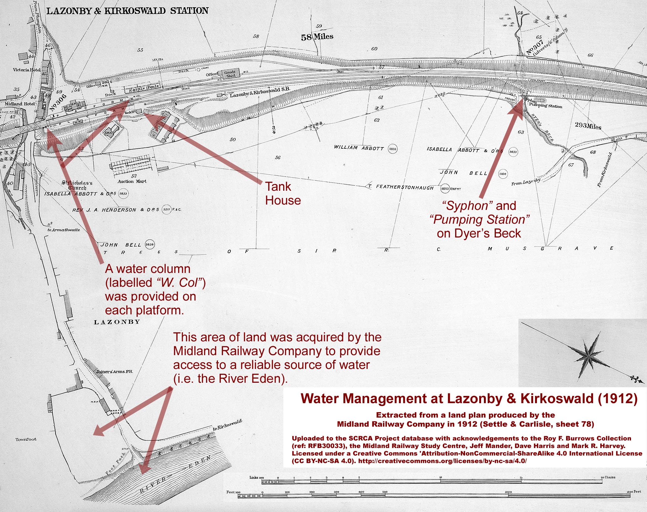
The land plan extracts below show how water was made available for steam locomotives at two very different locations on the Settle-Carlisle Railway.

Note on terminology and gender
Throughout this article, the traditional terms 'driver' and 'fireman' have been used. However, in the modern world, neither of these roles is restricted to a specific gender.
Acknowledgements
Research and text by Mark R. Harvey (© Mark R. Harvey, 2012-2022). Images as per the individual attributions / copyright notices.